Product Designs and Development
IEPC-2015-366 / ISTS-2015-b-366
Status of the Miniaturized Flow Control Unit uFCU
Joint Conference of 30th ISTS, 34th IEPC and 6th Nano-satellite Symposium · Hyogo-Kobe, Japan · 4–10 July 2015
Hans-Peter Harmann, Heiko Dartsch
2015
Flow Control
Qualification
Xenon
Abstract
The uFCU, pre-qualified at TRL5+ for electric propulsion systems, has been expanded to cover multiple flow ranges from 1 sccm micropropulsion to 100 sccm high-flow applications and validated through coupling tests with large radio frequency ion thrusters.
I. Introduction
Flow control units are key components of electric propulsion systems. AST Advanced Space Technologies GmbH developed a miniaturized flow control unit, the µFCU, in a program funded by the European Commission between 2011 and 2013, pre-qualified at unit level (TRL5+). The first µFCU was developed for small thrusters, delivering 1-8 sccm xenon at an inlet pressure of 2.2 bar; by varying the internal flow channel geometry, the µFCU can be optimized for a required flow range, with two subtypes under development – one for micropropulsion (1.0 sccm full scale at 1 bar) and one for larger thrusters (100 sccm at 2.2 bar). It has also been demonstrated that the range can be adjusted by inlet pressure alone, with the first µFCU design tested from 1.9 sccm at 0.8 bar to 45 sccm at 6.5 bar. In 2014, coupling tests with electric propulsion systems started to evaluate system integration aspects, with a first successful integration test on a large radio frequency ion thruster (RIT-22 of Airbus DS GmbH), and tests with a RIT-µX thruster for micropropulsion in preparation within an ESA project.
II. General Design
The µFCU is a gas flow regulator for propellant to the thruster, connected to a regulated gas feeding system, with two individually controlled outputs (typically one for the thruster, one for the neutralizer). The flow path board baseplate contains microchannels, with a row of three valves welded into the board, a row of three tube stubs providing mechanical interface, and round particle filter elements below; on the bottom side, access holes to the valves are closed by end caps, with markings and mounting holes at the corners. Key parameters of model “EQM3”: mass 63 g, size 46 x 54 mm, inlet pressure 1.0 to 6.0 bar, full-range flow 10 sccm at 2.3 bar, operating temperature -30°C to +80°C, non-operating -40°C to +100°C, operational voltage 24 V, average power < 2.5 W, particle filter 5µm in inlet and outlet, operational life > 50,000 hrs typical, control mode open-loop or closed-loop on thruster parameter (e.g. anode current), leakage < 10⁻⁶ scc/s GHe.
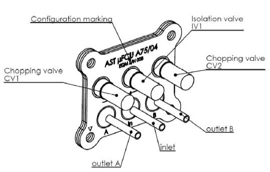
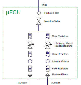
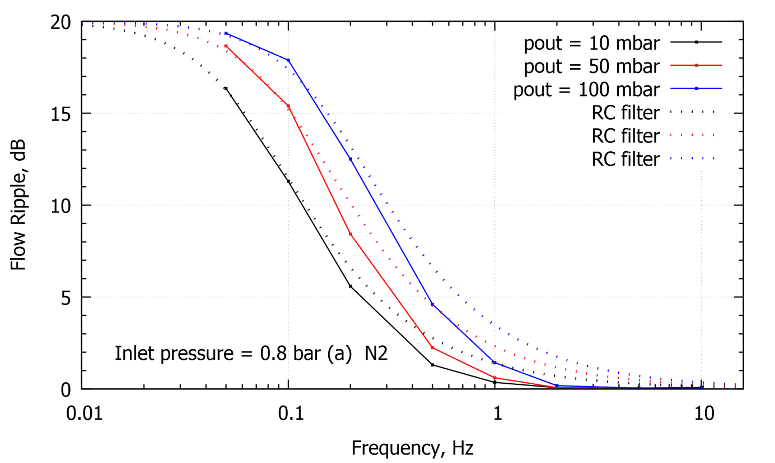
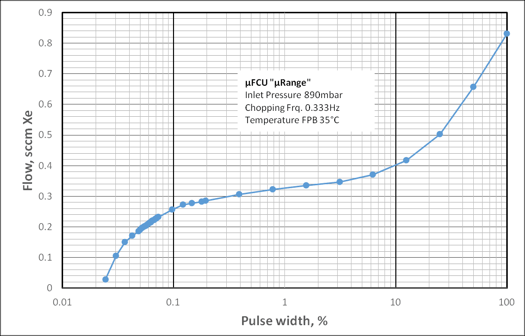
A common inlet line, protected by a 5µm particle filter, feeds an isolation valve shutting down flow to the µFCU; behind it the flow splits into individual control lines, each with flow restrictors, a chopping valve, and a nonlinear fluidic low-pass filter, with all valves driven at 24V in pull-in/hold operation. Chopping valves generate a pulsed gas flow, with average flow adjusted by pulse width and frequency (typically 1-3 Hz), smoothed by the fluidic low-pass filter to a steady, ripple-free flow. A µFCU with filters at reduced cut-off frequencies (0.33 Hz) was developed within ESA’s Euclid project to enlarge control range to very small flow rates below 0.2 sccm. The µFCU is designed for 1 to 6 bar(abs) but tested from 0.8 to 9 bar(abs), with the flow range changing linearly with inlet pressure.
III. Coupling Tests
Model “EQM3” is the working horse of the flow control unit development, originally designed for xenon flows of about 8-10 sccm full scale, tested for an extended range from 0.05 to above 60 sccm by adjusting inlet pressure, and used for coupling tests with gridded ion thrusters. The first coupling test with a RIT-22 took place at Giessen University in September 2014: the flow control unit was installed outside the vacuum chamber in parallel to the normally used commercial flow controller, controlled by AST’s unit tester equipment; after parameterizing the thruster, the gas supply was switched to the µFCU and the RIT-22 operated at all relevant working points with no ripple or other effects detected, in both open-loop and closed-loop modes (the latter using a parameter derived from RIT RFG power).
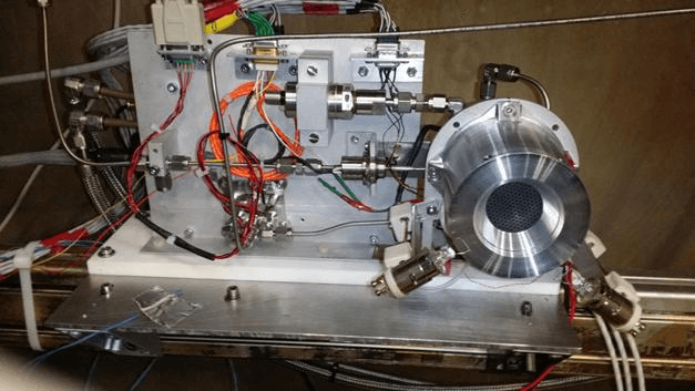
A second test campaign, also at Giessen University, investigated compatibility with a RIT-µX thruster, with the µFCU EQM3 flow range set to 1.7 sccm full range by reducing inlet pressure to 0.8 bar. At such small flow rates the step response is dominated by flow-line length between FCU and thruster, so the µFCU was placed inside the vacuum chamber close to the thruster with a line length of about 20 cm. The µFCU drove the thruster across its full operational range, down to about 0.4 sccm at the lowest limit of its throttle capability; further flow reduction was possible by lowering chopping frequency but increased flow ripple.
Model “µRange”
The development of the RIT-µX for micropropulsion, e.g. as a candidate for ESA’s Euclid mission, requires even lower flows down to 0.05 sccm, driving a new µFCU concept internally called “µRange” developed in a contract with ESA. The unit was designed and manufactured and, as of May 2015, was performing thermal vacuum acceptance tests before delivery to ESTEC for integration into a RIT-µX system. Factory tests showed the cut-off frequency of the fluidic filter significantly reduced, with no flow ripple appearing at 0.3 Hz operation.
IV. Conclusion
AST’s miniaturized flow control unit “µFCU” has grown mature. First coupling tests demonstrated it can easily be integrated into existing propulsion systems without major changes, and the full-scale flow range can be adjusted by inlet pressure, reducing the number of individual designs needed to cover different types of electric propulsion systems. A µFCU dedicated to micropropulsion systems has been manufactured and will be tested at ESTEC.
Paper No.
IEPC-2015-366 / ISTS-2015-b-366
Published
2015
Conference
Joint Conference of 30th ISTS, 34th IEPC and 6th Nano-satellite Symposium · Hyogo-Kobe, Japan · 4–10 July 2015
Authors
Hans-Peter Harmann, Heiko Dartsch
Keywords
flow control unit, miniaturized, xenon, electric propulsion, coupling test, RIT thruster, micropropulsion