Product Design Concepts
SP2022_244
Propellant Management Units for Electric Propulsion Thrusters in Series Production and in Update for New Applications
Space Propulsion 2022 · Estoril, Portugal · 9–13 May 2022
Marcel Berger, Hans-Peter Harmann
2022
Propellant Management
Pressure Regulation
Flow Control
Abstract
With over 600 flight units in orbit, AST presents the production status of its HP-FCU alongside new developments including redundant pressure regulators for the ESA Mars Sample Return mission and a high-pressure krypton-capable upgrade.
Over the last decade, AST Advanced Space Technologies GmbH has developed highly integrated fluid management devices for space propulsion systems; today over 400 units are flying in orbit with millions of flight hours proving the robustness of the design and production approach. AST’s designers challenged the classical concept of integrating discrete components on a spacecraft, reducing interfaces and AIT effort by combining fluidic functions in a single unit – just as surface-mounted devices (SMD) are integrated on printed circuit boards (PCB), AST’s fluidic components are placed on a flow path board (FPB), a multilayer stack of plates with integrated flow channels welded by diffusion bonding into a solid, vacuum-tight piece of stainless steel 316L with a 3D fluidic network.
2. Building Block Elements of AST’s Propellant Management Devices
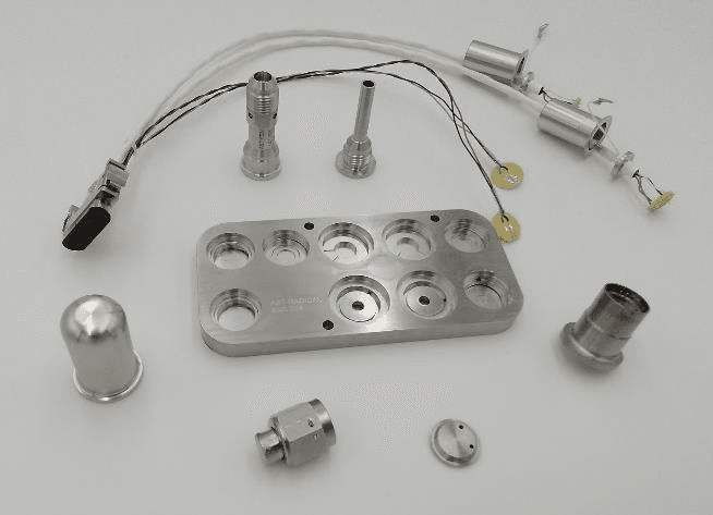
Building-block elements carry individual functions that can be arranged to customer needs. Reusing the same or similar component design on different products achieves high design flexibility at low individual effort, and most elements are interchangeable to maintain series-production stability while allowing economies of scale. The main elements are: the Flow Path Board (FPB), which connects all welded parts and contains flow restrictors; inlet/outlet tube stubs interconnecting spacecraft pipework with the FPB (5µm filter mesh, 11µm filtration rate); high-pressure/low-pressure valves for isolation or massflow/pressure control; high-/low-pressure sensors for closed-loop control input; an intermediate plenum for expansion and ripple reduction; and a harness interconnecting valves and sensors to spacecraft electrical infrastructure.
3. Electronic Pressure Regulator
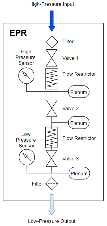
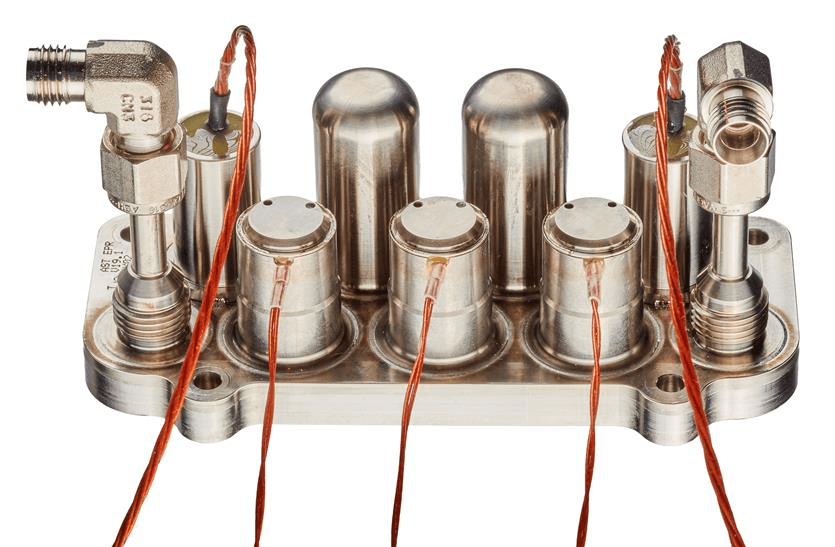
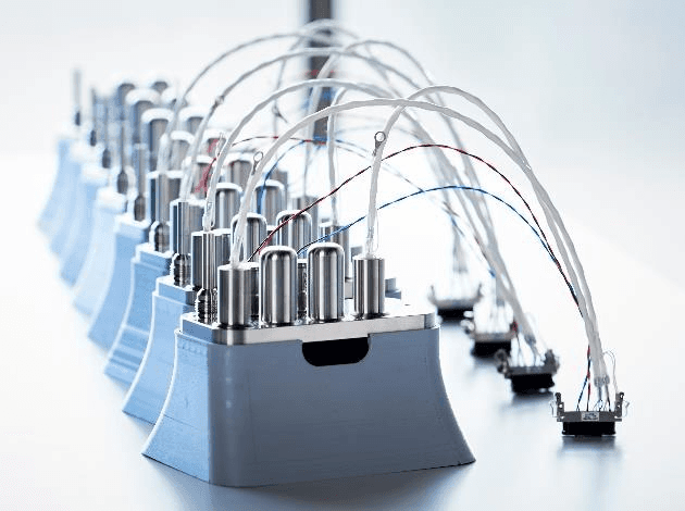
The Electronic Pressure Regulator (EPR) is a readily available, customizable product qualified in several configurations, based on a multi-stage pressure regulation concept with sequential inlet-pressure step-down. The EPR has been qualified to operate with inlet pressures up to 300 bar, allowing tank pressure drop down to about 5 bar while maintaining low-ripple output. As an all-welded design, external leakage is minimal and internal leakage is determined only by the three series valves. Performance: operating media GN2/GXe/GKr, operating pressure 5 to 300 bar, outlet pressure 1 to 5 bar, internal leakage < 10⁻⁵ sccs GHe, external leakage < 10⁻⁸ sccs GHe, max flow rates > 250 mg/s coarse / > 50 mg/s fine mode, pressure ripple < 20 mbar (fine mode), mass 0.65 kg. The final integrated EPR has the footprint of a modern smartphone at a mass below 900 g; a stand-alone flight driver-circuit design is currently under development to complement customer power electronics.
4. Low-Pressure Flow Control Unit
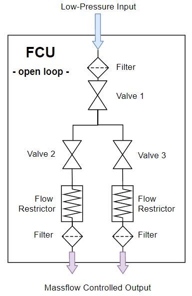
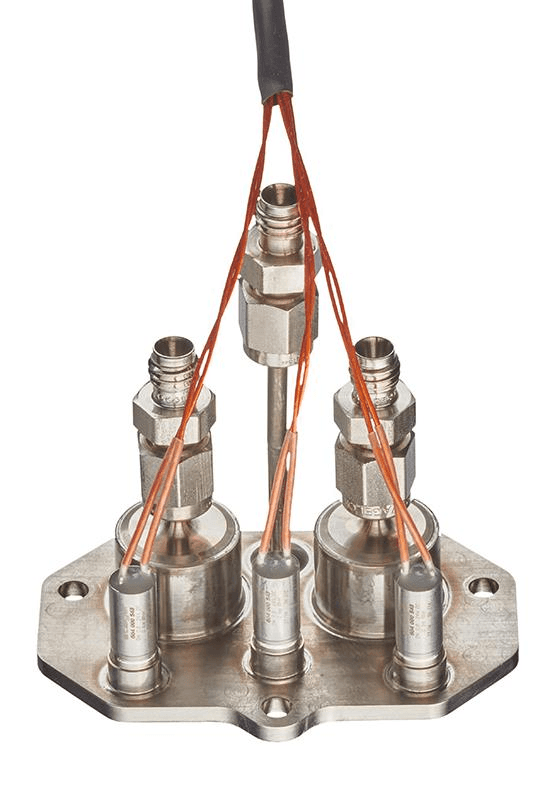
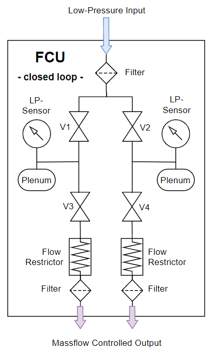
Coming from a pressure regulator, propellant flow needs precise control to deliver specific quantities to the thruster ionizing vessel and neutralizer/hollow cathode, with especially scientific missions demanding a large operational thrust range and flexibility. AST’s miniature Low-Pressure Flow Control Unit (LP-FCU) provides highly agile, accurate massflow control on a very small footprint, available in open-loop or closed-loop configurations using AST’s building-block elements. Its smaller FPB and miniature low-pressure valves keep the footprint smaller than a credit card while maintaining fine massflow control; pressure sensors and intermediate plenums can be added for closed-loop operation. Performance: operating media GXe (GKr, GN2, GHe), operating pressure 2 bar (0.5-8 bar), back-pressure selectable 0.3-0.8 bar, flow rates selectable e.g. 0.15-10 mg/s, flow ripple < 1%, mass < 0.07 kg (open-loop) / < 0.70 kg (closed-loop).
5. High-Pressure Flow Control Unit
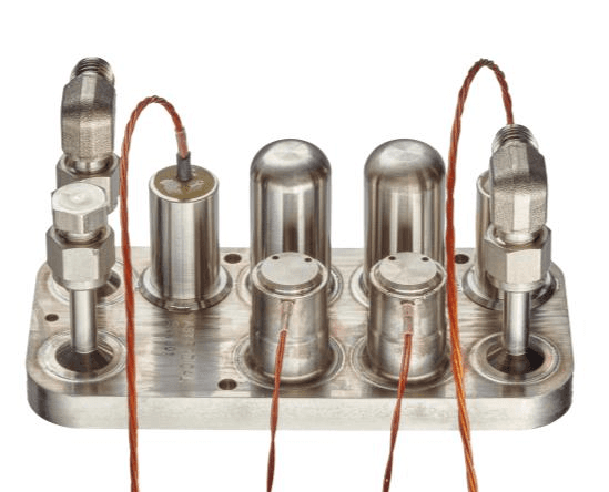
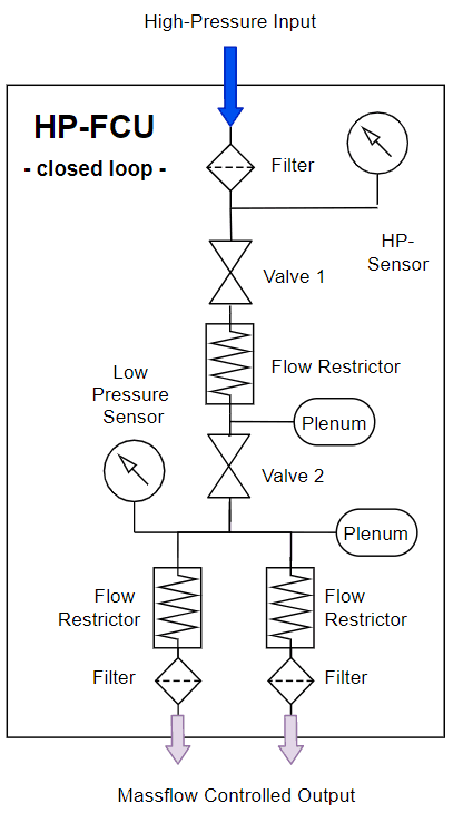
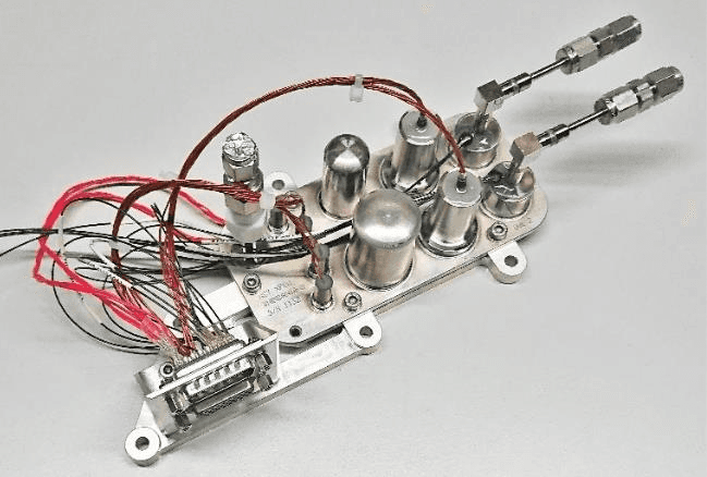
For propulsion systems using only one or two thrusters, the EPR and FCU functions can be combined into the High-Pressure Flow Control Unit (HP-FCU), also known as “RADICAL”, based on an easily adaptable but fixed split ratio with a single operating point (slightly adjustable in flight). Two binary solenoid valves and a fluidic low-pass filter convert the high-pressure inlet to a defined outlet flow, with the two valves forming double redundancy for leak tightness; this highly integrated design has been chosen to supply propellant to thrusters aboard several hundred OneWeb constellation satellites. Performance: operating media GXe, operating pressure 2 to 150 bar, flow rates selectable e.g. 1.5 mg/s, flow split ratio selectable (typically 10/1 anode-cathode), flow ripple < 1%, mass < 0.9 kg. The unit has been qualified for burst pressures up to 600 bar and tested to acceptance pressures of 225 bar, remaining fully operational and compliant afterward.
6. Successful Demonstration Through Coupling Tests
In the frame of European Commission partnership projects (EPIC), coupling tests were conducted successfully with multiple thrusters. EPR+LP-FCU and HP-FCU configurations have been tested in multiple setups since 2017 with Hall-Effect Thrusters, Gridded Ion Engines, HEMP Thrusters and Helicon Plasma Thrusters, spanning power ranges from a few hundred Watts to 20 kW with similar range in required massflows, with AST’s fluidic devices performing as expected from day one in nearly all cases.
7. Fluidic Management for Electric Propulsion Systems
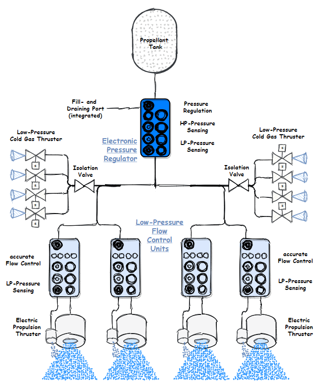
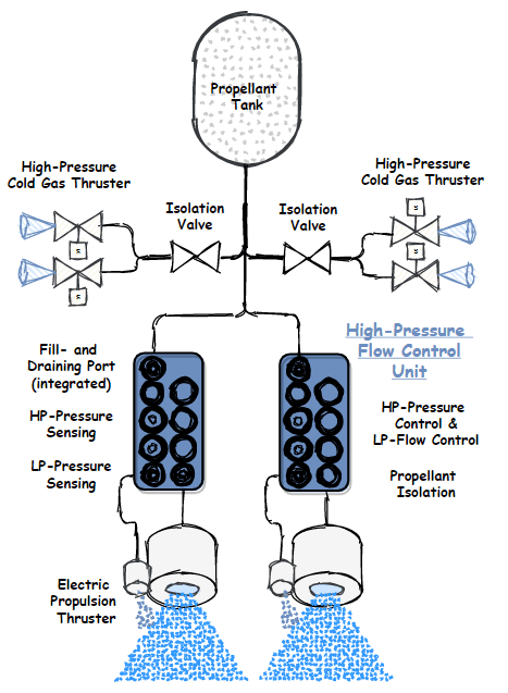
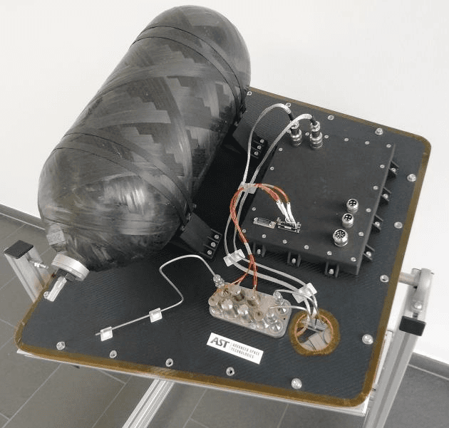
The fluidic equipment developed and qualified at AST allows propulsion system architects to define customized solutions based on industrialized space products, complemented by stand-alone fill-and-drain valves, pressure sensors, isolation valves and cold-gas thrusters. A classical system concept combines the EPR with a closed-loop FCU for multi-thruster missions; alternatively, the HP-FCU combines both functions in one device for low-cost missions operating one or two thrusters at a specific operating point, easing AIT efforts since only a few components need integration and testing at spacecraft level. Because the HP-FCU’s design focus is massflow control for a single EP thruster, it cannot support a low-pressure cold-gas thruster branch; instead, a High-Pressure Cold Gas Thruster operating in blow-down mode directly from the propellant tank is proposed for fine impulses in coarse attitude control (e.g. de-tumbling, safe-mode) and fast collision-avoidance manoeuvres.
8. Fluidic Management for Cold-Gas Propulsion Systems
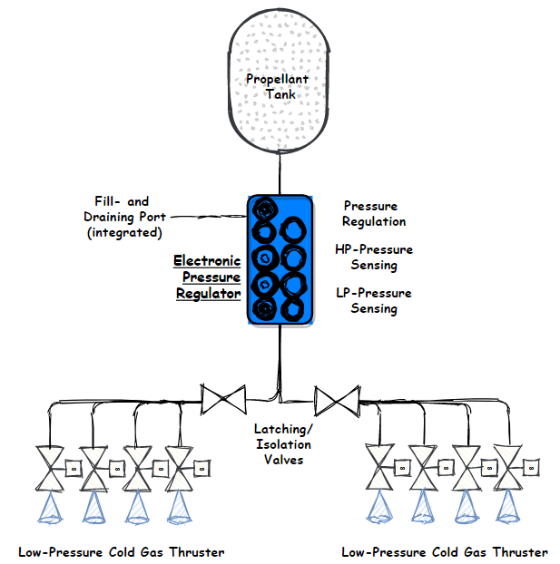
By embarking an EPR and a series of cold-gas thrusters, the simplest satellite propulsion system concept can be realized, with the EPR’s upstream high-pressure sensor providing propellant gauging and, optionally, a fill-and-drain valve, further simplifying the fluidic concept and minimizing spacecraft integration effort. The coldgas thruster for such a solution, currently under development at AST, is based on AST’s flight-heritage coldgas thruster design and sized to provide a nominal thrust level of about 50 mN at less than 2 bar inlet pressure.
9. Ongoing Developments and Customization
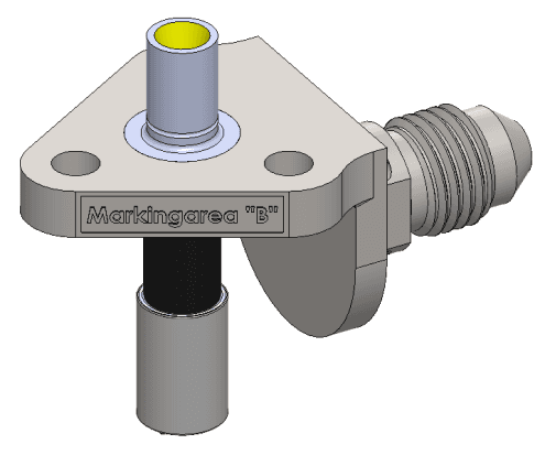
Due to continuously increasing Xenon procurement prices, market demand for Krypton-based electric propulsion is increasing. AST has therefore started a delta-development of its HP-FCU, supported by an ARTES C&G program, to qualify an upgraded design for MEOP of 300 bar (proof pressure > 450 bar) and demonstrated long-term operation and total throughput capability with Krypton, while maintaining the same fluidic architecture with adapted individual components to withstand higher operation and proof pressures. A key challenge is available test equipment, currently defined for up to 150 bar MEOP; a purpose-built, contaminant-free pressure compressor system is under development to enable acceptance and qualification tests above 300 bar Krypton pressure, with validation planned alongside the first HP-FCU article tests in summer 2022. Design options for the upgraded HP-FCU include an integrated fill-and-drain valve, selectable nominal outlet massflows, one or two outlet ports, tube-stubs with weld or screwed (AN) connections, optimization for high-throughput or low-massflow ripple, and thermal hardware selection. The fully industrialized approach, combined with AST’s established production line (up to 600 units per year), allows economies of scale and low unit prices in a reliable, high-pace production.
1. Introduction to AST’s Fluid-SMD Design Principle
1. Introduction to AST’s Fluid-SMD Design Principle
Over the last decade, AST Advanced Space Technologies GmbH has developed highly integrated fluid management devices for space propulsion systems; today over 400 units are flying in orbit with millions of flight hours proving the robustness of the design and production approach. AST’s designers challenged the classical concept of integrating discrete components on a spacecraft, reducing interfaces and AIT effort by combining fluidic functions in a single unit – just as surface-mounted devices (SMD) are integrated on printed circuit boards (PCB), AST’s fluidic components are placed on a flow path board (FPB), a multilayer stack of plates with integrated flow channels welded by diffusion bonding into a solid, vacuum-tight piece of stainless steel 316L with a 3D fluidic network.
2. Building Block Elements of AST’s Propellant Management Devices
Building-block elements carry individual functions that can be arranged to customer needs. Reusing the same or similar component design on different products achieves high design flexibility at low individual effort, and most elements are interchangeable to maintain series-production stability while allowing economies of scale. The main elements are: the Flow Path Board (FPB), which connects all welded parts and contains flow restrictors; inlet/outlet tube stubs interconnecting spacecraft pipework with the FPB (5µm filter mesh, 11µm filtration rate); high-pressure/low-pressure valves for isolation or massflow/pressure control; high-/low-pressure sensors for closed-loop control input; an intermediate plenum for expansion and ripple reduction; and a harness interconnecting valves and sensors to spacecraft electrical infrastructure.
3. Electronic Pressure Regulator
The Electronic Pressure Regulator (EPR) is a readily available, customizable product qualified in several configurations, based on a multi-stage pressure regulation concept with sequential inlet-pressure step-down. The EPR has been qualified to operate with inlet pressures up to 300 bar, allowing tank pressure drop down to about 5 bar while maintaining low-ripple output. As an all-welded design, external leakage is minimal and internal leakage is determined only by the three series valves. Performance: operating media GN2/GXe/GKr, operating pressure 5 to 300 bar, outlet pressure 1 to 5 bar, internal leakage < 10⁻⁵ sccs GHe, external leakage < 10⁻⁸ sccs GHe, max flow rates > 250 mg/s coarse / > 50 mg/s fine mode, pressure ripple < 20 mbar (fine mode), mass 0.65 kg. The final integrated EPR has the footprint of a modern smartphone at a mass below 900 g; a stand-alone flight driver-circuit design is currently under development to complement customer power electronics.
4. Low-Pressure Flow Control Unit
Coming from a pressure regulator, propellant flow needs precise control to deliver specific quantities to the thruster ionizing vessel and neutralizer/hollow cathode, with especially scientific missions demanding a large operational thrust range and flexibility. AST’s miniature Low-Pressure Flow Control Unit (LP-FCU) provides highly agile, accurate massflow control on a very small footprint, available in open-loop or closed-loop configurations using AST’s building-block elements. Its smaller FPB and miniature low-pressure valves keep the footprint smaller than a credit card while maintaining fine massflow control; pressure sensors and intermediate plenums can be added for closed-loop operation. Performance: operating media GXe (GKr, GN2, GHe), operating pressure 2 bar (0.5-8 bar), back-pressure selectable 0.3-0.8 bar, flow rates selectable e.g. 0.15-10 mg/s, flow ripple < 1%, mass < 0.07 kg (open-loop) / < 0.70 kg (closed-loop).
5. High-Pressure Flow Control Unit
For propulsion systems using only one or two thrusters, the EPR and FCU functions can be combined into the High-Pressure Flow Control Unit (HP-FCU), also known as “RADICAL”, based on an easily adaptable but fixed split ratio with a single operating point (slightly adjustable in flight). Two binary solenoid valves and a fluidic low-pass filter convert the high-pressure inlet to a defined outlet flow, with the two valves forming double redundancy for leak tightness; this highly integrated design has been chosen to supply propellant to thrusters aboard several hundred OneWeb constellation satellites. Performance: operating media GXe, operating pressure 2 to 150 bar, flow rates selectable e.g. 1.5 mg/s, flow split ratio selectable (typically 10/1 anode-cathode), flow ripple < 1%, mass < 0.9 kg. The unit has been qualified for burst pressures up to 600 bar and tested to acceptance pressures of 225 bar, remaining fully operational and compliant afterward.
6. Successful Demonstration Through Coupling Tests
In the frame of European Commission partnership projects (EPIC), coupling tests were conducted successfully with multiple thrusters. EPR+LP-FCU and HP-FCU configurations have been tested in multiple setups since 2017 with Hall-Effect Thrusters, Gridded Ion Engines, HEMP Thrusters and Helicon Plasma Thrusters, spanning power ranges from a few hundred Watts to 20 kW with similar range in required massflows, with AST’s fluidic devices performing as expected from day one in nearly all cases.
7. Fluidic Management for Electric Propulsion Systems
The fluidic equipment developed and qualified at AST allows propulsion system architects to define customized solutions based on industrialized space products, complemented by stand-alone fill-and-drain valves, pressure sensors, isolation valves and cold-gas thrusters. A classical system concept combines the EPR with a closed-loop FCU for multi-thruster missions; alternatively, the HP-FCU combines both functions in one device for low-cost missions operating one or two thrusters at a specific operating point, easing AIT efforts since only a few components need integration and testing at spacecraft level. Because the HP-FCU’s design focus is massflow control for a single EP thruster, it cannot support a low-pressure cold-gas thruster branch; instead, a High-Pressure Cold Gas Thruster operating in blow-down mode directly from the propellant tank is proposed for fine impulses in coarse attitude control (e.g. de-tumbling, safe-mode) and fast collision-avoidance manoeuvres.
8. Fluidic Management for Cold-Gas Propulsion Systems
By embarking an EPR and a series of cold-gas thrusters, the simplest satellite propulsion system concept can be realized, with the EPR’s upstream high-pressure sensor providing propellant gauging and, optionally, a fill-and-drain valve, further simplifying the fluidic concept and minimizing spacecraft integration effort. The coldgas thruster for such a solution, currently under development at AST, is based on AST’s flight-heritage coldgas thruster design and sized to provide a nominal thrust level of about 50 mN at less than 2 bar inlet pressure.
9. Ongoing Developments and Customization
Due to continuously increasing Xenon procurement prices, market demand for Krypton-based electric propulsion is increasing. AST has therefore started a delta-development of its HP-FCU, supported by an ARTES C&G program, to qualify an upgraded design for MEOP of 300 bar (proof pressure > 450 bar) and demonstrated long-term operation and total throughput capability with Krypton, while maintaining the same fluidic architecture with adapted individual components to withstand higher operation and proof pressures. A key challenge is available test equipment, currently defined for up to 150 bar MEOP; a purpose-built, contaminant-free pressure compressor system is under development to enable acceptance and qualification tests above 300 bar Krypton pressure, with validation planned alongside the first HP-FCU article tests in summer 2022. Design options for the upgraded HP-FCU include an integrated fill-and-drain valve, selectable nominal outlet massflows, one or two outlet ports, tube-stubs with weld or screwed (AN) connections, optimization for high-throughput or low-massflow ripple, and thermal hardware selection. The fully industrialized approach, combined with AST’s established production line (up to 600 units per year), allows economies of scale and low unit prices in a reliable, high-pace production.
Paper No.
SP2022_244
Published
2022
Conference
Space Propulsion 2022 · Estoril, Portugal · 9–13 May 2022
Authors
Marcel Berger, Hans-Peter Harmann
Keywords
propellant management, Electronic Pressure Regulator, Flow Control Unit, HP-FCU, cold gas thruster, building block elements