Product Designs and Development
IEPC-2013-227
uFCU - A Miniaturized Flow Control Unit for Xenon
33rd International Electric Propulsion Conference · The George Washington University, Washington, D.C., USA · 6–10 October 2013
H.-P. Harmann, S. Rothaus, G. Wanot
2013
Flow Control
Xenon
Electric Propulsion
Abstract
AST developed the uFCU, a 62 g miniaturized xenon flow control unit using solenoid valves in pulse-width modulation and a flow path board with integrated microchannels, supporting flow ranges from 0.01 to 100 sccm.
I. Introduction
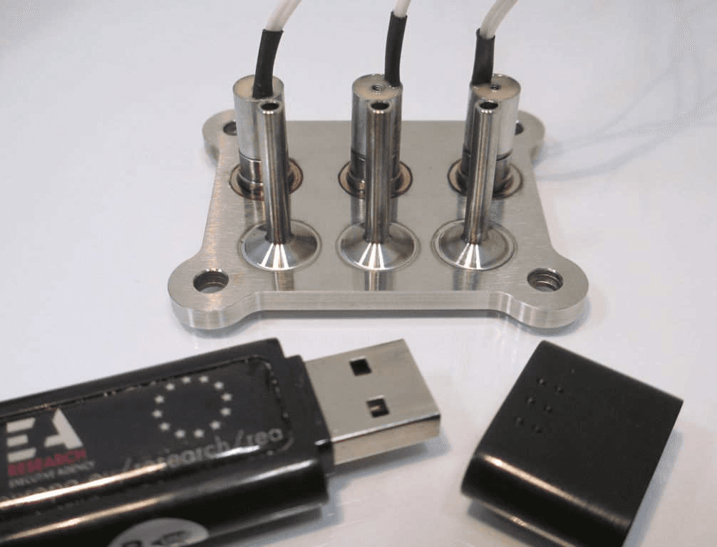
A consortium of five European partners led by AST Advanced Space Technologies GmbH (AST) developed a new miniaturized flow control unit, the µFCU, in a 22-month project (December 2012 to September 2013) funded by the European Commission’s 7th Framework Program. The new design uses solenoid valves in pulse-width modulation to control gas flow, with fluidic interconnection realized by a flow path board with integrated microchannels; the flow control range can be designed for flows from 0.01 sccm to 100 sccm. A standard configuration comes with two independently controlled outlet flow lines with different ranges for thruster and neutralizer, includes 5µm inlet and outlet filters, and the all-welded device weighs a total of 62 g within a 54 x 46 x 25 mm envelope.
II. Objectives
Electric propulsion is a key technology for future missions, and typical flow control units have a mass of 400 g to 1 kg per thruster – significant for spacecraft with up to 24 thrusters like LISA. Six major objectives were defined: (1) FCU system mass less than 100 g per thruster (thruster + neutralizer line); (2) only components of European origin, since Europe lacked its own high-TRL technology for miniaturized flow control units and most suppliers relied on valves of US origin; (3) achieve internal leakage rates below 10⁻⁶ scc/s GHe over lifetime and extend the temperature range beyond +90°C; (4) demonstrate operation with at least two flow ranges (1.5 sccm and 10-50 sccm full-scale Xe); (5) reach TRL 5; and (6) use a modular concept and keep the design simple.
III. Design Description
The µFCU project bases on a “spin-in” development approach of ITAR-free European components, adapted from ground applications with good reliability data, converted for space through material exchange, cleaning and cleanliness processes and an intensive test and verification campaign at component and unit level. Two EQMs were manufactured in mid-2013: EQM01 underwent performance and thermal vacuum tests, and EQM02 underwent performance and vibration tests plus proof pressure and thermal vacuum testing, together completing all qualification-relevant tests except a full lifetime test.
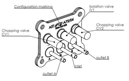
The baseline µFCU has two independently controlled flow lines with commandable flow rates, sufficient to supply two independent thrusters or one thruster/neutralizer pair (SPT, HEMPT, RIT), and has no sensor element to keep system complexity low, with the control loop closed using a signal from the thruster (e.g. anode current). Gas enters through a 5µm filtered inlet port, is stopped or established by an inlet isolation valve, then splits into two branches where a chopping valve in pulse-width or frequency modulation controls average flow into a microchannel fluidic low-pass filter that eliminates ripple at the outlet, embedded in the flow path board (FPB), comparable to a PCB in electronics. Both output paths are filtered by 5µm particle filters. The valve manufacturer’s heritage in leakage-tester valves contributes to ultra-low internal leakage, giving a double serial redundancy against propellant loss; internal leakage is specified better than 10⁻⁶ sccs GHe, typically an order of magnitude lower. PWM/FM operation avoids the drifting working point of proportional valves and, with a higher chopping frequency (1-5 Hz) combined with the fluidic low-pass filter, eliminates the large flow ripple typical of “bang/bang” controls.
Component Development
The valves use an advanced plate-anchor technology without bearing friction. A set of 30 valves with three seal elastomers was tested in an accelerated wear test with thermal cycling from -40°C to +110°C and flows exceeding 1000 sccm at ~2 bar differential pressure using Argon and Xenon. First wear effects appeared after 300 million cycles, and the internal leakage requirement was exceeded by most valves after 350 million cycles; the test continued to 700 million cycles without valve failure before being stopped, from which the minimum cycle operational lifetime capability at 3 Hz was estimated. The flow path board (FPB), similar in function to a PCB, uses stainless steel plates with engraved microchannels bonded into a vacuum-tight stack forming a three-dimensional network of channels and component ports. Particle filters, made entirely of 316L stainless steel with a 5µm woven mesh, are designed for surface-mount integration to the FPB and verified by bubble testing.
IV. System Integration Aspects
Integrating the µFCU requires a pressure pre-regulator to reduce tank inlet pressure to 1-3 bar (nominal 2 bar); the FCU must be able to open its flow lines against a pressure-relief-valve set point plus margin to vent pressure down to nominal (demonstrated up to 12 bar). The µFCU also has an inherent self-limiting maximum flow feature: fluidic microchannels in the FPB can only carry a maximum gas flow, choking at 145% of the specified full-scale flow at nominal pressure even if inlet pressure is further increased. System integration concepts include redundant configurations combining two µFCUs (e.g. one line of each supplying the anode in parallel redundancy, the second supplying two neutralizer cathodes for SPT, HEMPT or RIT), or using two standard µFCUs for three required flow lines in electron-bombardment thrusters, with further lines addable by extending the FPB as long as isolation-valve flow capacity is not exceeded.
V. Key Performance Figures
Key operating parameters: nominal flow range 0.1-1.5 sccm Xe or 1-10 sccm Xe (other values achievable via different internal flow channel sizes); self-limiting at 145% of nominal flow range; two independent flow lines; flow ripple < 1%; operating pressure range 1 to 3 bar (nominal 2 bar); MEOP for venting 8 bar (12 bar demonstrated); proof pressure 12 bar; operational temperature -30°C to +90°C, non-operational -40°C to +110°C; internal leakage < 10⁻⁶ sccs GHe, external leakage < 10⁻⁸ sccs GHe over lifetime cycling; lifetime > 300 million cycles (equivalent to 28,000 operating hours at 3 Hz); mass 62 g; dimensions 54 x 46 x 25 mm; all-welded 316L stainless steel with Viton wetted seals; TRL 5+, pre-qualified; ITAR free.
VI. Status
Component and process development finished successfully. Two EQMs were built and tested in a pre-qualification program covering thermal vacuum, thermal cycling and proof pressure (EQM01) and vibration (EQM02), reaching TRL-5 and covering a large portion of TRL-6.
VII. Conclusion
A new miniaturized xenon flow control unit has been developed and pre-qualified by a project consortium led by AST. All relevant tests have been successfully performed to qualification levels on two engineering and qualification models. The new ITAR-free design allows a significant reduction in mass and size, and the flat design with access to all welding positions, low operational complexity and relaxed driving-electronics requirements give the µFCU great potential for system cost reduction, now ready for a formal qualification program.
Paper No.
IEPC-2013-227
Published
2013
Conference
33rd International Electric Propulsion Conference · The George Washington University, Washington, D.C., USA · 6–10 October 2013
Authors
H.-P. Harmann, S. Rothaus, G. Wanot
Keywords
flow control unit, miniaturized, xenon, electric propulsion, pulse width modulation, flow path board, solenoid valve