Product Specifications
Low-Pressure Flow Control Unit (LP-FCU) - Product Datasheet
AST Advanced Space Technologies GmbH
2024
Flow Control
Electric Propulsion
Propellant Management
Abstract
AST's LP-FCU provides open-loop flow control for electric propulsion systems using pulse-width modulation for individual output line control, with a 10:1 throttling range from a regulated low-pressure inlet.
Product Overview
The Low Pressure Flow Control Unit (LP-FCU) is a compact open-loop flow control unit fed by an upstream pressure regulator with a regulated inlet pressure in the range of 1.0 bar to 4.0 bar. In non-operating mode, the FCU provides a double barrier for propellant isolation; in operating mode, it supplies a massflow at a regulated flow rate to the thruster and the corresponding neutralizer. Inlet and outlets of the FCU are protected by particle filters.
All components are fluidically interconnected through the Flow Path Board (FPB), a stainless-steel element with integrated flow channels, welded by electron beam into the FPB – a design that significantly reduces complexity and improves the unit’s in-orbit robustness. Inlet and outlet ports are equipped with filter mesh to assure valve function after ground handling. The flow rate is controlled by actuation of the FCU valves: during operation the common isolation valve is held permanently open, while the flow resistor in each of the two flow lines converts the common inlet pressure into an average flow rate, individually controllable per flow line by actuating the corresponding regulation valve in a pulse-width-modulation scheme at a typical frequency of 1 to 5 Hz.
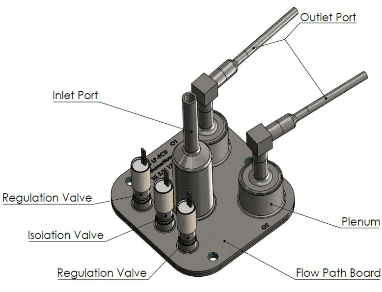
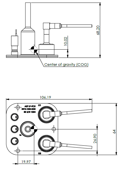
The throttling range of both flow lines can be 1-to-10 depending on the chosen nominal massflow, allowing a very wide range of operational flows with the same hardware in orbit. The LP-FCU can be equipped with foil heaters on the underside of the FPB to maintain constant temperature conditions; with the very low power consumption of the LP-valves, dissipation on the unit is below 2 W. The unit is mounted to a structure through three M4 screws with thermal washers compatible to the satellite thermal control system.
LP-FCU Characteristics
Operating media: Xe, Kr, Ar and others (Xe in qualification). Inlet pressure MEOP 5 bar (maximum operation); inlet pressure EOL 1 bar, flow dependent. Proof pressure 1.5× MEOP (design value > 7.5 bar); burst pressure > 2.5× MEOP (design value > 12.5 bar). Nominal anode and cathode flow 0.1 mg to 10 mg/s, selectable by design. Throttle range better than 1 to 10, settable during operation. Propellant throughput capability > 100 kg, depending on flow level. Regulation precision better than 1%, depending on electronics and control loop. Output flow ripple < ±2.5%, depending on electronics bandwidth and line volume. Flow response time up to 10 s (up) and up to 30 s (down), to achieve 95% of a full-scale step at the line outlet port (e.g. during start-up).
Internal leakage < 1×10⁻⁵ sccs GHe and external leakage < 1×10⁻⁷ sccs GHe, both verified during acceptance tests. Thermal range -20°C to +95°C non-operational (including qualification margin) and +40°C to +50°C operational (full performance), with -10°C to +65°C for cold start (limited performance, heater recommended). Fluid filtration rate 11µm (5µm mesh at inlet and outlet). Mass under 200 g without harness, including margin. Average power consumption under 2 W, depending on valve actuation frequency. Valve operating voltage 24V (minimum pull-in voltage required for motorization margin, 50% hold-voltage). Vibration qualification levels 20 gRMS on all three axes, and shock qualification loads of 3000 g at frequencies higher than 1000 Hz. Radiation tolerance is 10 Mrad TID.
Paper No.
Published
2024
Conference
Authors
AST Advanced Space Technologies GmbH
Keywords
low-pressure flow control unit, LP-FCU, flow control, electric propulsion, xenon, pulse width modulation, flow path board