Ground Support & Measurement Equipment
IEPC-2015-257 / ISTS-2015-b-257
Low Drift Thrust Balance with High Resolution
34th International Electric Propulsion Conference / 30th ISTS Joint Conference · Hyogo-Kobe, Japan · 4–10 July 2015
Hans-Peter Harmann, Heiko Dartsch, Ellen Werner
2015
Thrust Balance
Measurement Equipment
Testing
Abstract
AST and DLR developed a small thrust balance for thrusters up to 2 kg, covering 0.1 mN to 1 N and demonstrating a long-term drift below 250 uN over 27 hours in a non-vacuum laboratory environment with minimal external decoupling.
I. Introduction
AST Advanced Space Technologies GmbH, in cooperation with Deutsches Zentrum für Luft- und Raumfahrt e.V. (DLR), developed a small thrust balance for thrusters with a mass of up to 2 kg. Its operation under vacuum conditions has already been successfully demonstrated during thruster measurement campaigns at DLR, and the balance is now part of the standard equipment at the DLR site in Göttingen, designated for integration into the STG-CT test facility. This paper reports test results obtained at AST showing the capabilities of the thrust balance in its present state.
II. Thrust Balance Design
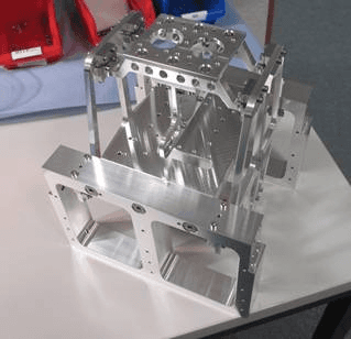
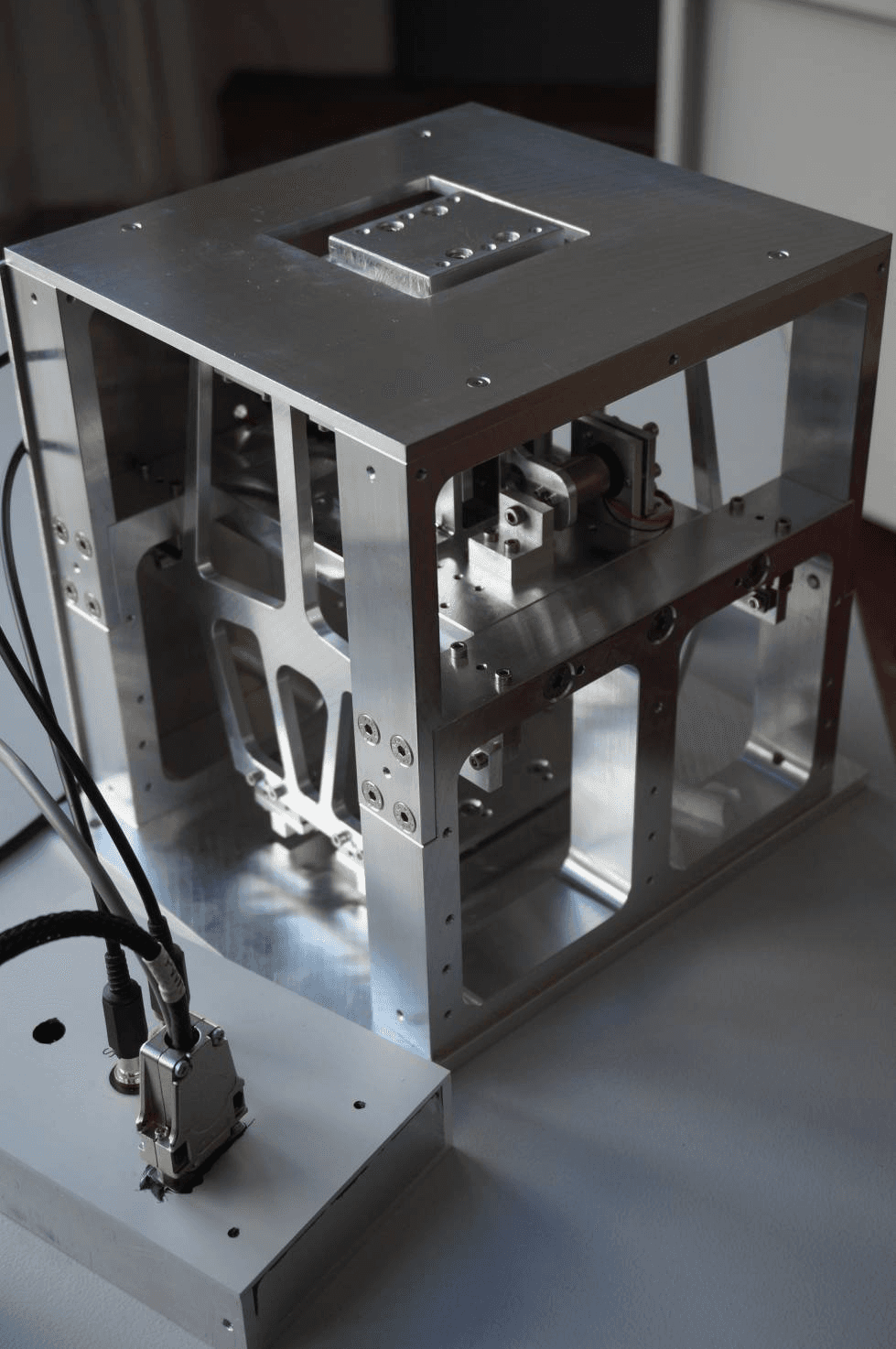
The AST thrust balance is of the counter-balanced, displacement-compensated type using a fast voice-coil actuator for force compensation, with all mechanical and key electronic components designed by AST and improved over several development cycles. The balance has a measuring capability from 0.1 mN to 1000 mN, optimized to show best performance from 1 mN to 250 mN. The structure, based on a parallelogram pendulum, is highly insensitive to external disturbances due to its particular mechanical design, so most measurement applications require no vibration damping tables; this low sensitivity to environmental influences is also a reason for the balance’s very low drift over time, allowing long-term measurement without intermediate offset compensation. Displacement is detected by a capacitive sensor and actively compensated by closed-loop PID control, with parameters selectable for either fast-response or low-noise/high-precision measurement.
III. In-Situ Calibration Capability
Besides the voice-coil actuator used for active force compensation, a second identical actuator provides in-situ calibration, applying an arbitrary test force to the balance at any time without generating additional disturbances. Proportionality constants for coil-current-to-force conversion were determined on a micro scale for both actuators prior to integration; the second actuator can be used to check for any deviation in the ratio of these constants, indicating malfunction or drift (aging) over time, since it is less affected by aging than the actuator used in normal operation, being unused during regular operation.
IV. Performance
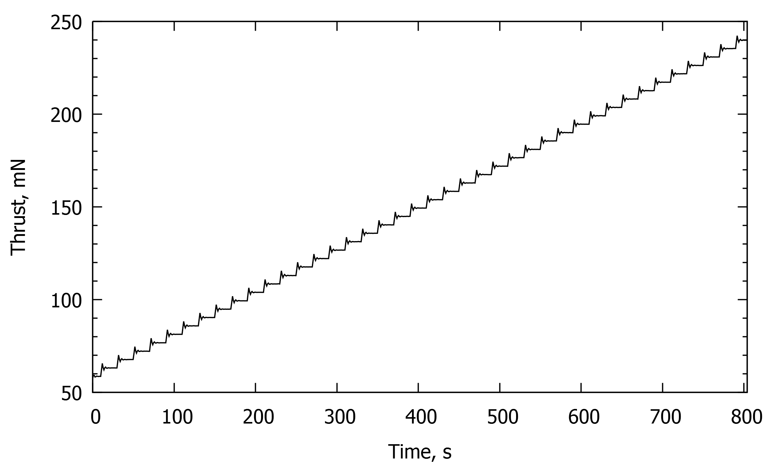
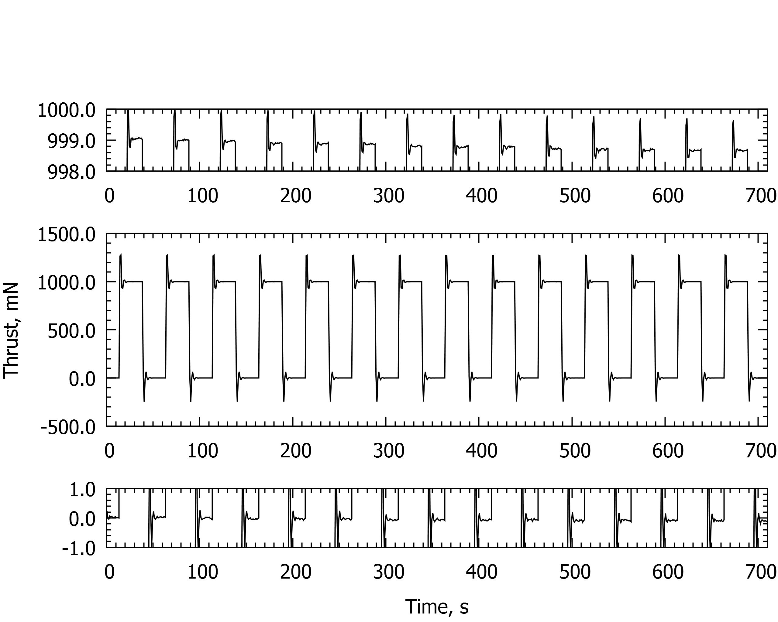
Data presented was obtained during tests at AST under ambient conditions, with the balance on a standard laboratory table without special decoupling precautions except a plastic box cover to reduce air-movement interaction; test forces were applied via the second voice-coil actuator. In high-sensitivity mode, small-signal response to a force alternating between 0 and 10 mN showed some overshoot/undershoot at each transition (due to limited-bandwidth high-precision operation reducing noise floor), with stability at each force plateau far better than 0.1 mN (< 1% of measured thrust), holding for reproducibility and overall drift. For large-signal response (0 to 1 N, the upper limit of extended measurement capability), deviation between corresponding plateaus plus overall drift for the complete measurement added up to less than 0.5 mN (< 0.05% of measured thrust level).
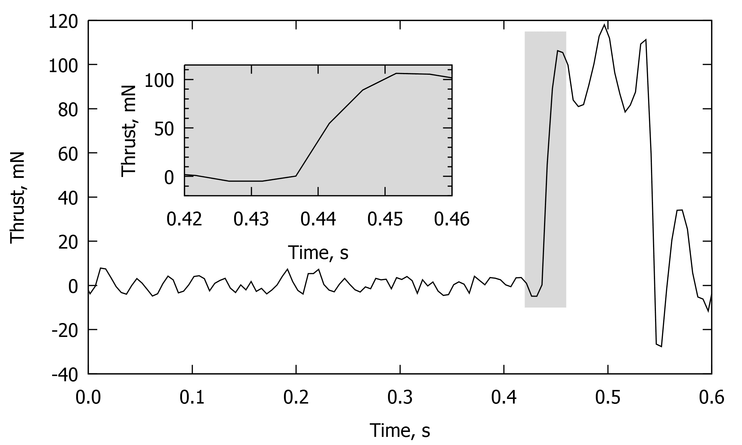
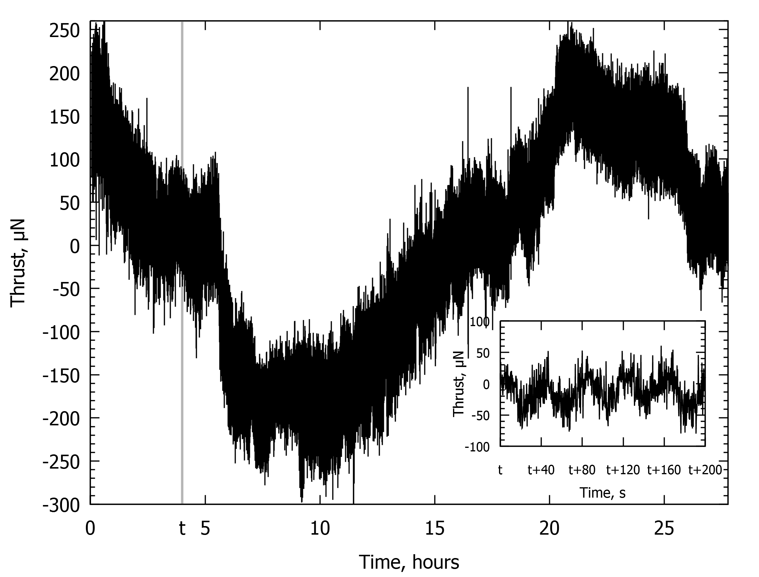
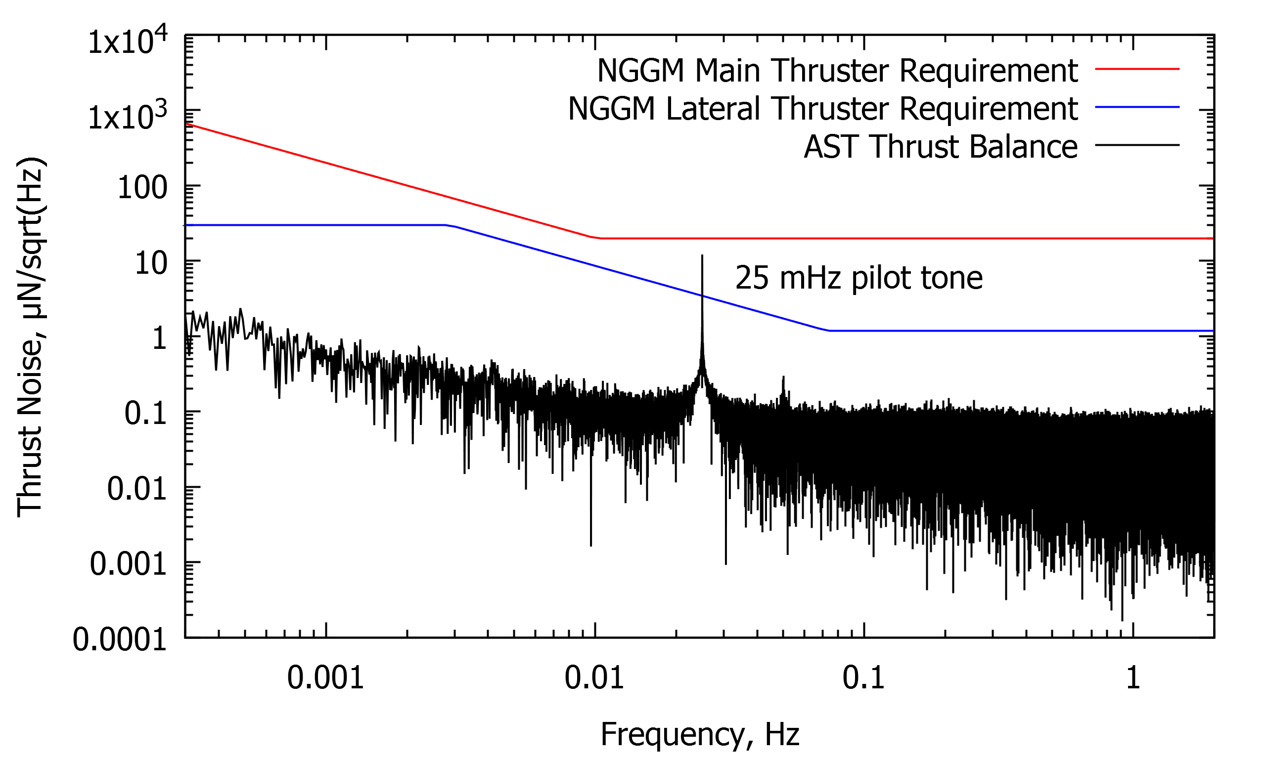
In fast-response measurement mode, with bandwidth increased in software, the balance resolved rectangular thrust pulses of 100 mN magnitude, 100 ms duration, at a 1 Hz repetition rate; high dynamic mode shows more noise than high-sensitivity mode, though the main noise contribution was highly reproduced at each pulse rather than random, with a rising-edge time constant of about 10 ms determined from a close-up view. For noise-floor measurement, a long-duration test over 27 hours (with a sinusoidal pilot tone of 40 µN amplitude at 25 mHz for reference) showed overall signal drift staying within ±250 µN for the complete period – less than ±0.1% of the full-scale reading relative to the balance’s nominal 0-250 mN operational range – with the main drift contribution correlated to room-temperature change due to poor decoupling from the environment, suggesting further reduction is possible with better isolation. Thrust noise density, derived via FFT of the signal autocorrelation, was compared against two Next Generation Gravity Mission (NGGM) thrust-noise requirement curves for reference.


V. First Measurement Application
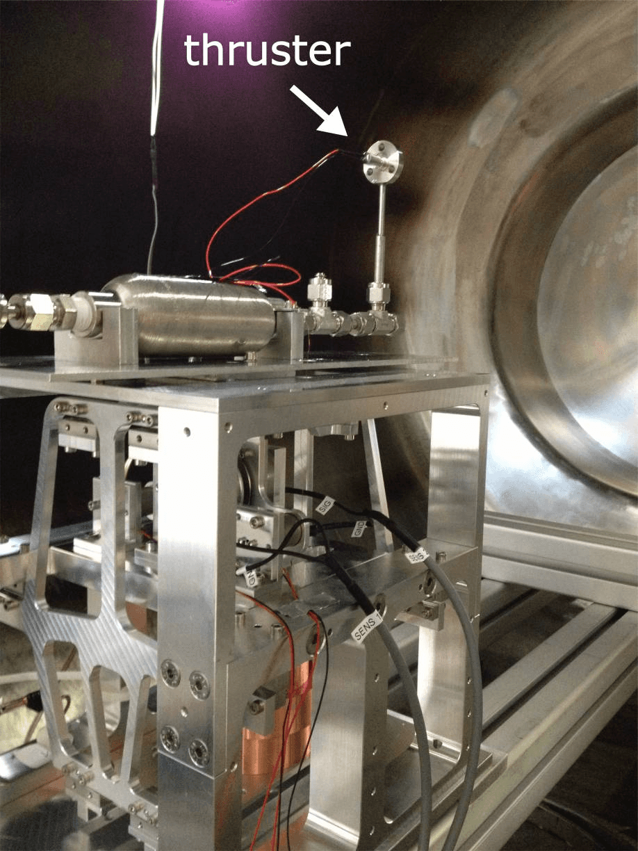
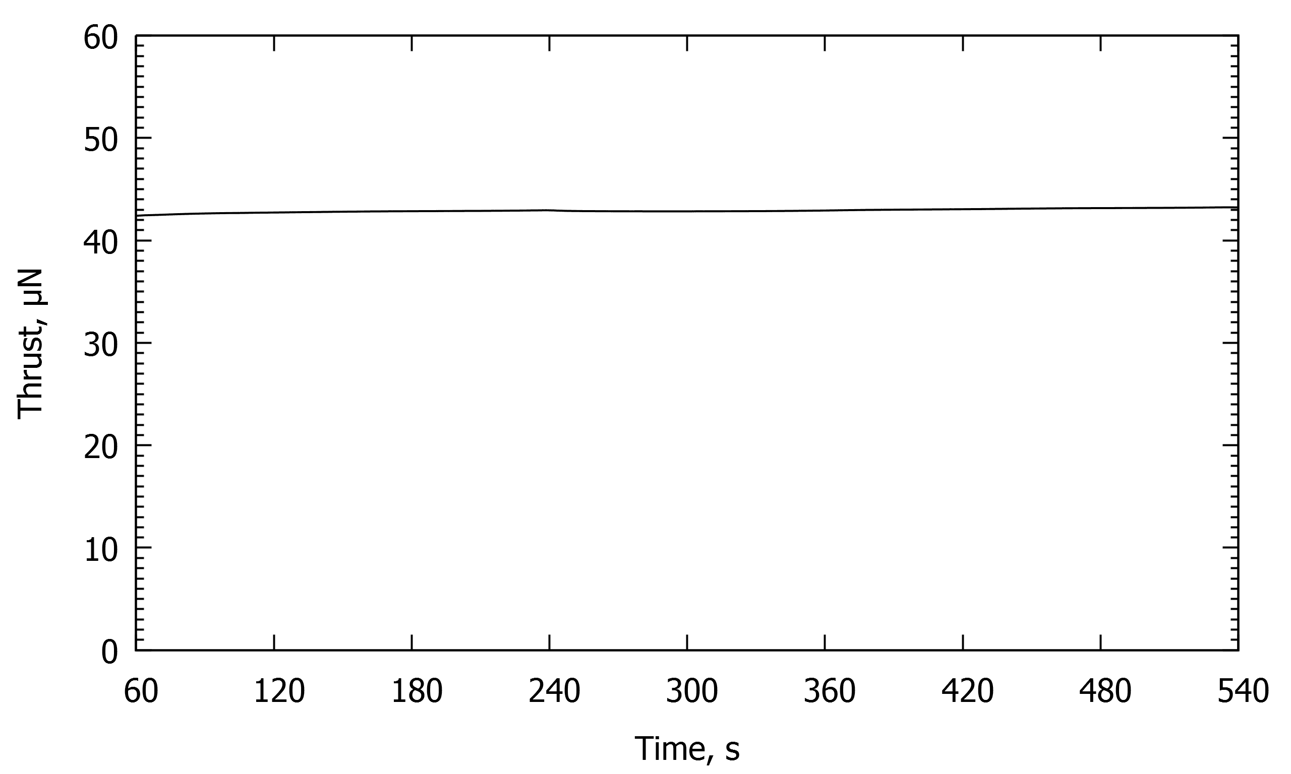
One of the first real-world applications was determining the specific impulse (ISP) of a cold gas thruster manufactured by AST, performed within the STG-MT test facility at the DLR Göttingen site. The thruster was mounted on the balance inside the vacuum chamber, supplied with nitrogen through a flexible tube at a constant inlet pressure of 1.5 bar(a), giving a measured mass flow of 2960 sccm (61.6 mg/s). The thrust signal was recorded during repeated firings, with the thruster switched off between firings to allow thrust to return to zero. Across seven individual firing tests, thrust levels ranged from 42.3 to 43.1 mN, with calculated ISP values from 69.9 to 71.2 s, giving an average ISP of 70.4 s ± 0.5 s for the AST nitrogen cold gas thruster at a mass flow of 61.6 mg/s.
VI. Outlook
While the AST thrust balance in its present state surpasses its design goals, further improvements to resolution and noise are considered possible, as the mechanical construction does not seem to have reached its limitations. A new version based on a very similar mechanical design, with improved electronic components, is being built by AST; the current voice-coil actuator generates force from -1.8 N to 1.8 N with an intrinsic 16-bit resolution enhanced by interpolation, and the new version will use higher-resolution components for improved performance across the full measurement range up to 1 N. A new voice-coil current source dedicated to thrust-noise measurements, covering a smaller thrust range for significantly improved resolution and less noise, is also planned, along with low-noise electronic parts at critical circuit sections to further reduce the overall noise floor. The new balance will additionally include a second, independent in-situ calibration device based on a different physical principle than the voice-coil actuator, providing two independent calibration methods and therefore high accuracy for absolute thrust measurement.
Paper No.
IEPC-2015-257 / ISTS-2015-b-257
Published
2015
Conference
34th International Electric Propulsion Conference / 30th ISTS Joint Conference · Hyogo-Kobe, Japan · 4–10 July 2015
Authors
Hans-Peter Harmann, Heiko Dartsch, Ellen Werner
Keywords
thrust balance, high resolution, low drift, thrust measurement, voice coil actuator, cold gas thruster