Product Design Concepts
SP2024_211
High Pressure Flow Control Units for Electric Propulsion Modules
Space Propulsion 2024 · Glasgow, Scotland · 20–23 May 2024
Thomas Brus, Marcel Berger
2024
Flow Control
Electric Propulsion
Serial Production
Abstract
AST's HP-FCU delivers a compact, scalable flow control and pressure regulation system for electric propulsion modules, already deployed in hundreds of systems in LEO. This paper presents the qualification status of the upgraded HP-FCU 2.0 for krypton operation above 300 bar MEOP.
1. Introduction
In the last decade, the space market is experiencing a rapidly growing demand for small satellites with strong focus on low-cost and serial production. Especially for constellation purposes, efficient electric propulsion modules using reliable propellant flow control components with high production rates are required. The HP-FCU designed and produced by AST fulfils these requirements by using a surface mounted device (SMD) approach. Similar to the design of electronics, where components are integrated on printed circuit boards (PCB), AST uses a flow path board (FPB), containing all necessary fluidic interconnections to mount all fluidic components, such as sensors, valves and volumes.
This design principle provides a reduced number of interfaces. All integrated components are automized electron beam welded to ensure high reliability and leak tightness. The assembly on the FPB leads to a compact design, which can be easily integrated and produced in series production. Therefore, the unit is suited for applications in various EP-subsystems, especially for constellation purposes. It is suitable for any type of ion thruster (GIE, HEMPT, HET…) with all noble gases.
2. HP-FCU Definition
The HP-FCU is a flow control unit designed for high pressure applications. It is based on building blocks with long lead items manufactured and stored in high quantities, enabling short delivery times. Currently, hundreds of customized units of the first generation HP-FCU design operate in LEO, providing a strong heritage for its successor HP-FCU 2.0.
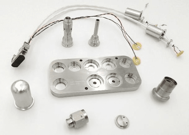
The HP-FCU is a two-stage flow control unit, used to regulate the spacecraft’s tank pressure to the required pressure and mass flow for electric thrusters.
The HP-FCU consists of the following elements:
Flow Path Board (FPB): containing all welded components and fluidic interconnections
Inlet Tube Stub: connecting the HP-FCU to the S/C pipework; equipped with 5 µm filter mesh
High-/Low-Pressure Valves: realizing the mass flow and pressure control, as well as propellant isolation for double leak tightness
Plena: allowing intermediate expansion to reduce pressure ripple
High-/Low-Pressure Sensors: allowing the gauging of the tank pressure and input measurements for pressure control
Outlets: connecting the HP-FCU to the thruster anode/cathode and/or neutralizer line

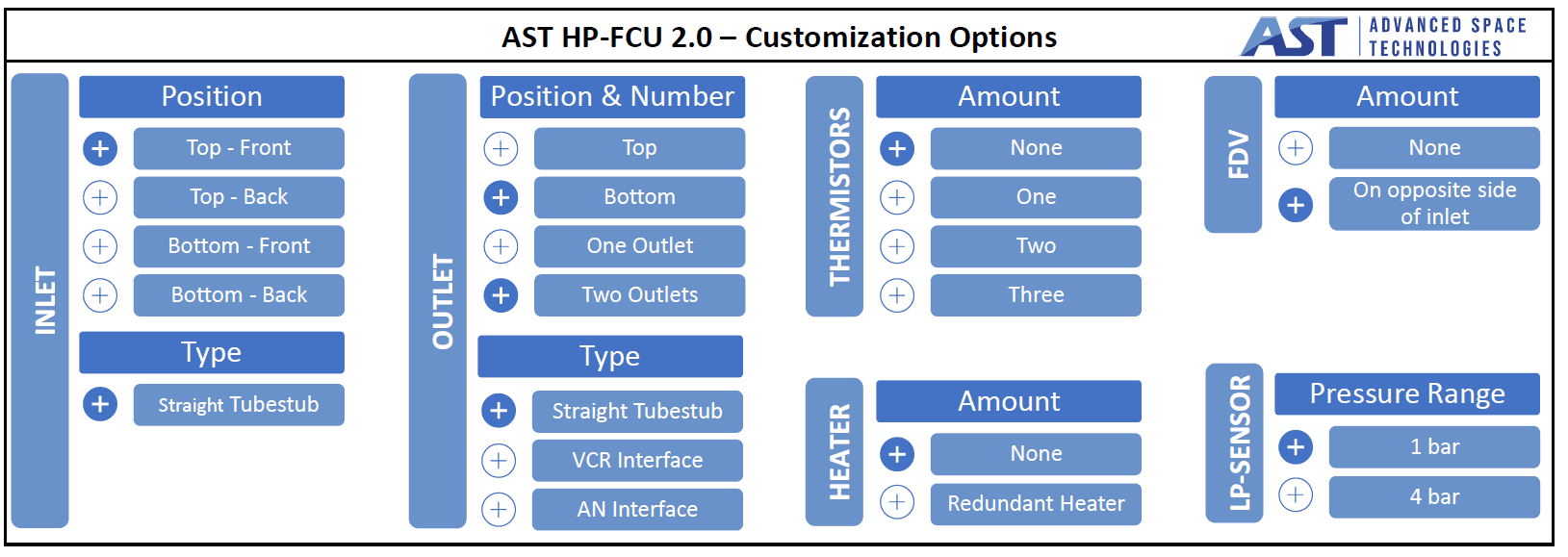
Compared to its predecessor the design is developed further to allow for higher inlet pressures. Therefore, the usage of other noble gases such as Krypton, which requires higher storage pressures, is possible. Additionally, the updated design allows for an easy configuration of the unit, regarding the position and type of outlets, volume of plena and required setpoints. Therefore, the HP-FCU can be produced in various configurations, depending on the customer’s needs.

3. Qualification Status of HP-FCU
Following the updated design for the HP-FCU, a complete qualification of the unit is performed. The qualification is part of the ARTES program by the European Space Agency (ESA). For the qualification two different configurations of the unit were considered, one with all components on the upper side and one with outlets on the lower side and equipped with a fill and drain valve (FDV).
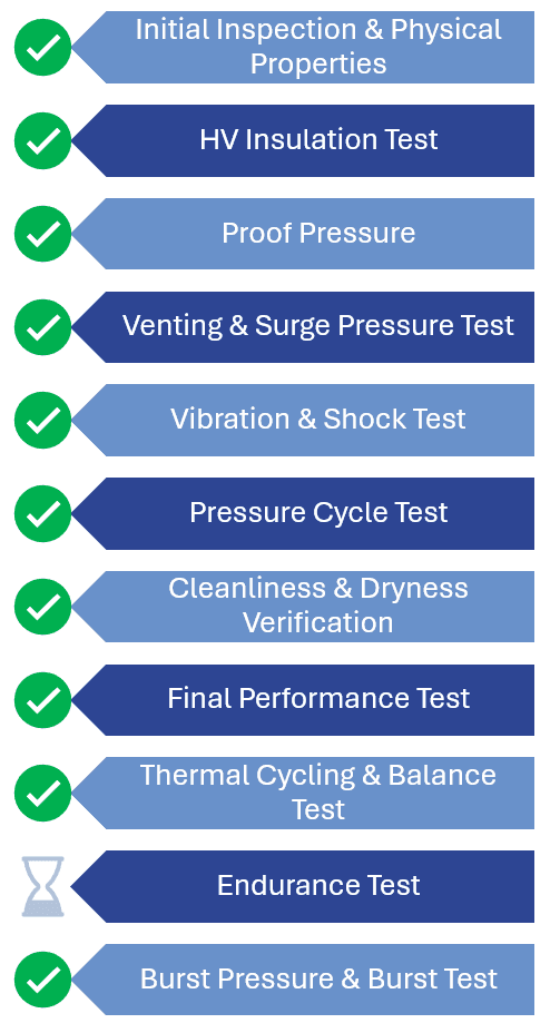
As can be seen, environmental tests were successfully performed. After each stress test of the unit a health check, including tests of electric parameters, internal and external leakage and a pressure sensor calibration verification, was carried out. With this procedure it is ensured that the absolved stress tests do not affect the unit’s characteristics. At the beginning and the end of the test campaign a performance test was done to verify that all stress tests did not influence the performance. Parallel to the tests on unit level, further investigations were executed on component level, such as lifecycle testing of the valves.
The HP-FCU was subject to vibration and shock testing, while being pressurized at 290 bar. The unit was exposed to sinusoidal vibration up to 24 g at 100 Hz and random vibration for each axis with an overall level of 27.2 grms. The shock test was performed using the ringing plate method for three levels (20g at 100 Hz and 2000 g at 1.000 and 10.000 Hz) in each axis. Thermal testing was conducted with cycling and thermal balance tests. The thermal cycling test was performed under vacuum with eleven cycles between -10 °C and +65 °C. During the thermal balance test, it was shown that under hot operational case conditions the valve’s coil temperature does not exceed 110 °C. HV insulation tests and cleanliness and dryness verifications were performed.
All relevant pressure tests were completed. The proof pressure test showed that a pressure of 1.5x MEOP is endured by the unit, with a MEOP of 320 bar for the high pressure section and 4 bar for the low pressure section. Venting and surge pressure tests were successfully carried out. These tests verified that the HP-FCU withstands internal pressure levels down to vacuum under external ambient conditions for ten times without exceeding the internal leakage rate. Furthermore, it is confirmed that no degradation is evident when the unit is exposed 12 times to a sudden pressure increase from 0 bar to MEOP at the inlet (valves closed). In addition to these 12 surge pressure cycles, the unit was subjected to 48 further cycles, without sudden increase, between ambient and MEOP to simulate pressure cycles due to tank loading and unloading operations.
During the qualification leakage tests it was evaluated that the internal and external leakage rates do not exceed the required leakage rates. The unit underwent these tests as part of the health check after each stress test, without relevant deviation in the leakage rates. For one of the qualification models the burst pressure test was absolved, leading to a burst pressure of at least 1000 bar. The endurance test for validating the lifetime is currently ongoing on the second qualification model. This test shall verify that a required total mass throughput of 33 kg krypton at realistic tank pressure can be realized. Additionally, on component level a lifecycle test was performed for the valve operation, showing that more than 2 million actuations are endured for varying temperature and pressure conditions.
The functional and performance tests of the flow control unit are performed using krypton, compressed up to 320 bar. The goal is to reach a targeted mass flow, considering realistic back pressures. As illustrated, the HP-FCU delivers a good performance over a wide range of inlet pressures. The target flow can be achieved for both, high and low pressures.
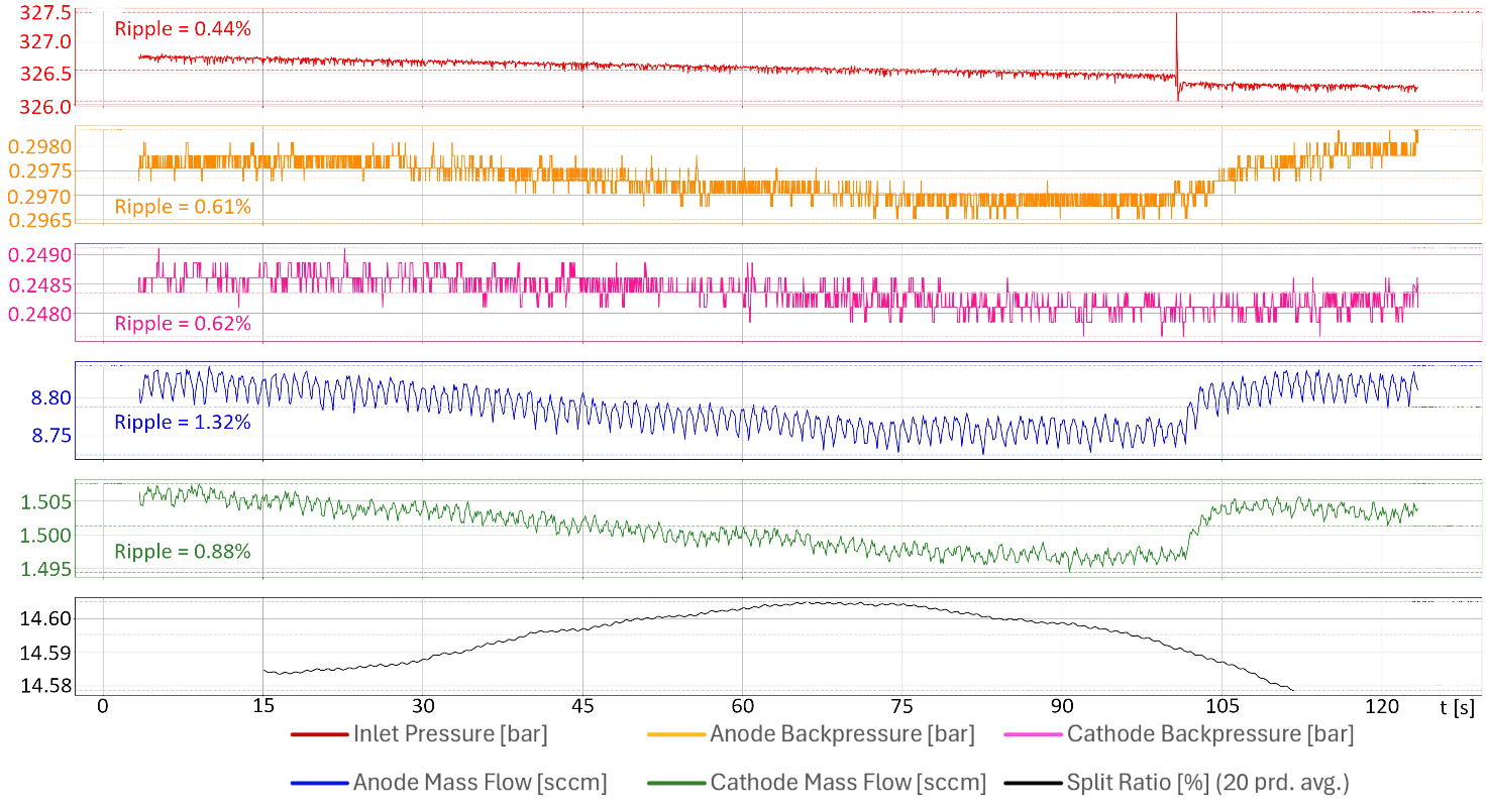
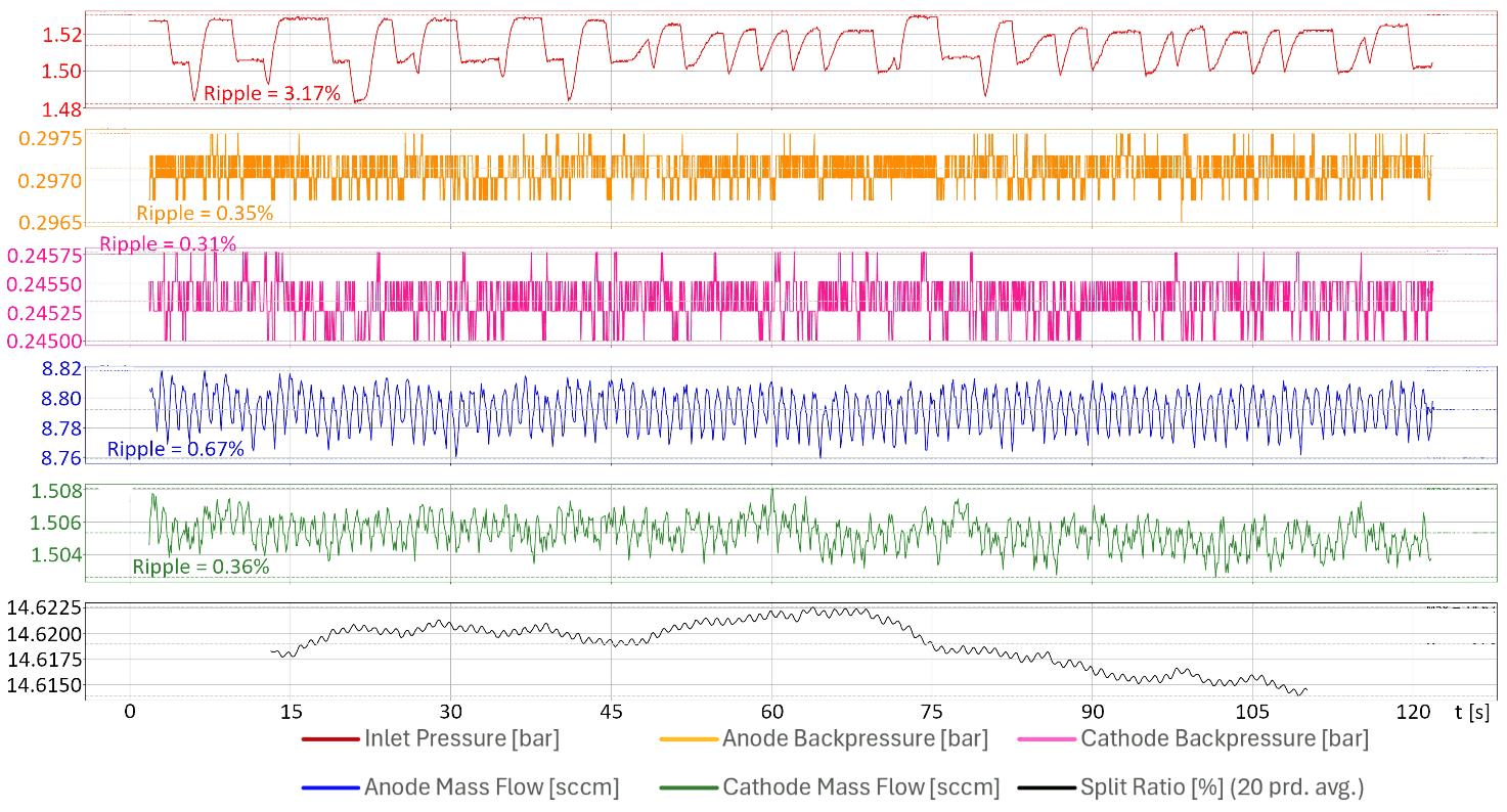
Looking at the curves, the opening of the first of the two valves, used for the two-stage pressure control on the HP-FCU, can be recognized by the dip in the inlet pressure. The opening of the second valve can be seen directly in the flow or backpressure ripple. The ripple is calculated as the ratio of the difference between the maximum flow (FLOWmax) and the minimum flow (FLOWmin) to the average flow (FLOWavg). It can be observed that the maximum mass flow ripple is always below 2%, for both MEOP and end of life (EOL) conditions.
4. EP-Subsystem Application
The high demand for satellites, particularly for large satellite constellations, requires the development of simplified EP-Subsystems, that can be produced at high rates of production. In traditional spacecraft development, the propulsion subsystem is customized for each satellite and consists of fluidic components such as valves or sensors, connected by piping and integrated into the satellite structure. However, the excessive effort required for the integration and testing of the propulsion system is not suitable for high scale series production.
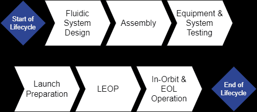
In contrast, the compact building-block design of the HP-FCU enables a simplification of the propulsion module. Therefore, the following chapter describes, on the basis of an exemplary EP-subsystem, how the HP-FCU can be implemented in novel subsystems and which aspects must be considered for different development stages. The consideration follows the life cycle of the subsystem chronologically, starting with a detailed evaluation of the design with respect to fluidic, electrical, thermal and mechanical aspects, describing the assembly, integration and test phase (AIT) and the launch and early operation phase (LEOP) and ending with the operational phase.
4.1. Design of EP-Subsystem with HP-FCU
The design of EP-Subsystem modules follows a general approach for developing S/C subsystems starting with the analysis of needs and deriving the key performance requirements. With respect to the propulsion subsystem the necessary propulsion functions must be determined, differentiating between the need for orbit insertion, orbit maintenance, attitude control, evasive manoeuvres or controlled de-orbiting. Requirements such as thrust levels, specific impulse, duty cycles or mission life lead to the selection and sizing of the type of thruster, tank and the corresponding EP-Subsystem.
Following the identification of the general subsystem components, such as the thruster and the tank, the detailed elaboration and accommodation of the subsystem with all required interfaces and components is performed, including the propellant management system. The choice of the HP-FCU for propellant regulation and distribution enables a variable realization of the EP-Subsystem design. The configuration of the flow controller can be adapted to the chosen arrangement.
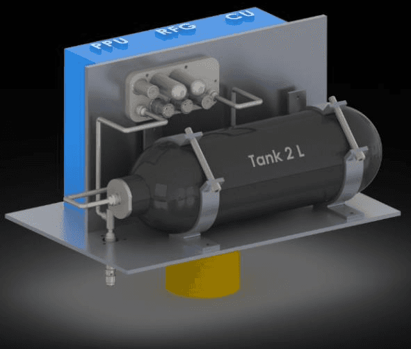
Design A features a compact design built around a shear wall, and design B which uses a flat arrangement of the system. For both designs a different configuration of ASTs HP-FCU is chosen. In design A the HP-FCU is not accessible from the outside. Therefore, a configuration is used in this arrangement, where all components are placed on the upper side of the FPB to allow for a flat mounting of the unit on the shear wall. Since the unit is not accessible, a standalone FDV is added to the subsystem, to allow for the filling and draining of the tank.
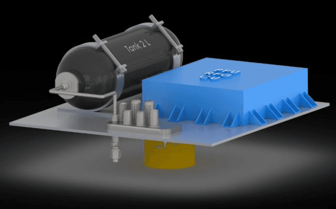
Design B uses a configuration of the HP-FCU with an integrated FDV. The unit is mounted on the backside of a structural panel which is reachable from the outside. Therefore, the propellant tank can be filled directly through the unit without the need of a standalone FDV. In this configuration also the outlets are placed at the bottom of the FPB for a direct feed through of the downstream lines through the panel, to reduce the pipework to the thruster. These examples show only two of the numerous ways to realize the EP-Subsystem design. Besides the arrangement of the components on the panel, multiple aspects regarding fluidic, electrical, thermal and mechanical design must be considered for the development of the subsystem.
Fluidic Design
In the EP-Subsystem the HP-FCU is the connecting element between the propellant tank and the electric thruster. Therefore, the choice of propellant management system has a great influence on the thruster’s performance. The basic fluidic architecture of a system using the HP-FCU consists of a tank, the HP-FCU as fluidic management system, a PPU for the electric control, piping and a thruster. The design can be extended with the inclusion of cold gas thrusters or adapted to a design with multiple thrusters with corresponding FCUs.
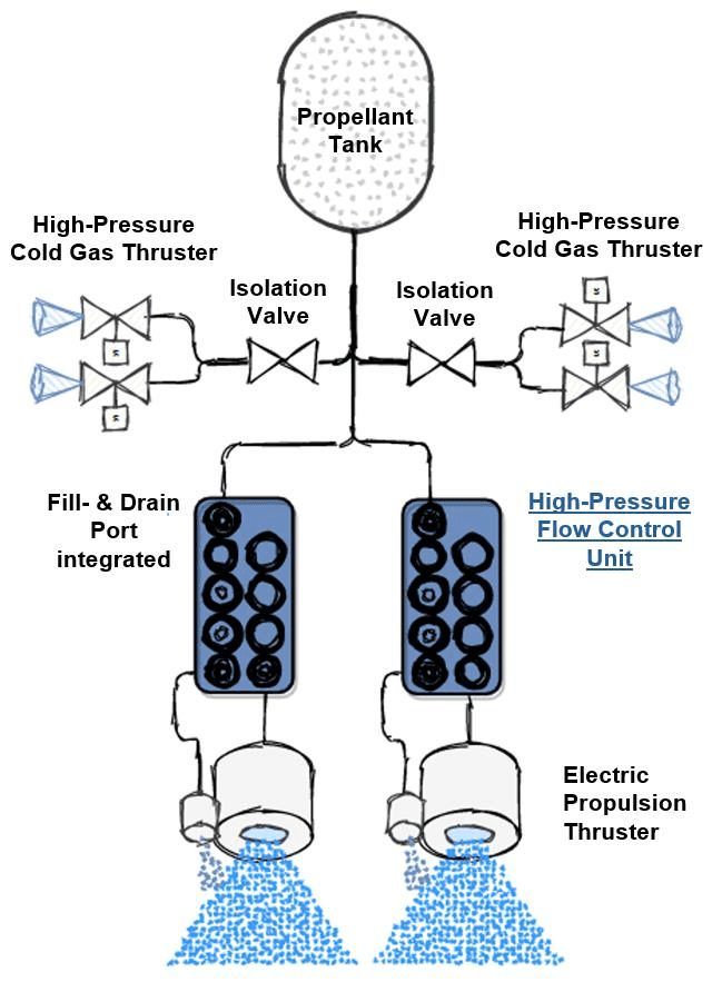
One decision to be made is the choice of propellant. Generally, the HP-FCU handles all types of noble gases. In the past, usually xenon was the choice for electric propulsion systems. The first generation of the HP-FCU has extensive heritage using this gas, with millions of in-orbit hours of operation. Due to the high procurement costs of xenon, krypton is increasingly used as alternative propellant. However, it must be considered that with the choice for krypton, a gas with lower density is substituting the higher density xenon. Without enlarging the tank volume, krypton must be stored at higher pressures, to compensate for its lower density. At the same time this represents another advantage of this noble gas since in contrast to xenon it is possible to increase krypton to pressures above 300 bar with reasonable effort. Nevertheless, these elevated pressures must be considered in the design of the subsystem, such as for the tank’s structural integrity and fluidic interconnections. The second generation HP-FCU will be qualified for a MEOP of 320 bar, allowing the use of krypton as propellant.
Besides the choice of propellant type, also the purity of the used gas is a relevant factor for the systems design. The HP-FCU is equipped with 5 µm particle filter meshes, with 11 µm particle filtration rates, at each fluidic interconnection (inlet, FDV, outlets). For small propulsion systems, using high purity gases, the flow controller’s filters may be sufficient to guarantee the required propellant cleanliness. However, with increasing size of the subsystem or for less pure input gas, additional system filters might be necessary. A system analysis with focus on filter retention capacity is recommended.
A further aspect to take into account is the fluidic interconnection. While in the high pressure part welded interfaces are applied, the connection on thruster side is more flexible. An orbital welded interface is also possible downstream of the HP-FCU, but screwed connections are an option as well. A special consideration is necessary with respect to vibration (anti-rotation lock) but screwed interfaces enable a simplification regarding AIT. While the leak tightness is secured for low pressures, a disassembly of the thruster connection during test and integration is still possible. Furthermore, a crimp connection is realizable.
Electrical Design
The HP-FCU can be delivered with different harness options, with flying leads or various connectors. The unit itself is not equipped with active electronics. It requires external electronic components. The control algorithm for the unit can be customized and implemented into the PPU. The electrical connection is necessary for the switching of the valves. The valves are usually supplied with a pull-in voltage of 24 V (variation possible to reach required motorization factor). However, it must be considered that the electronics enable the down switching of the voltage to 12 V after 10 to 50 ms to decrease the heat dissipation of the valves. Additionally, the electronics should be equipped with a valve interlock, preventing the two valves from opening at the same time.
The HP-FCU is equipped with a 350 bar high-pressure sensor for inlet pressure monitoring and either a 1 or 4 bar low-pressure sensor, used for the closed-loop pressure regulation. Both sensors must be supplied with a constant voltage of 10 V. The electronics must be able to amplify the low-level signal of the sensors. The unit provides a grounding hole for the addition of a grounding strap.
Thermal Design
Due to the described switching for the valves, from 24 V pull-in to 12 V hold voltage, the valves and therefore the unit have only low-level dissipation. An adiabatic accommodation is possible. During the thermal design of the EP-subsystem the environmental temperature limits must be considered. The operational limits for the unit are -10 °C to +65 °C (non-operational -30 °C to +65 °C). However, the minimum temperature to reach the HP-FCUs best performance is 27 °C. If desired, it is possible to integrate the HP-FCU to the thermal control system (TCS) of the spacecraft. For this purpose, the unit can be equipped with a surface area heater on the bottom of the unit and an additional temperature sensor on the temperature reference point.
Mechanical Design
Another aspect to be considered is the mechanical design. The integration of the subsystem is simplified by the compact design. It is recommendable to place tank, HP-FCU and thruster in spatial proximity to reduce the pipework and its mechanical connection to the S/C structure. Generally, it must be ensured that the system provides sufficient connection points to the structure to prevent dynamic loads on fluidic interfaces. The HP-FCU is proven robust against a wide range of mechanical loads.
For the mechanical interface of the HP-FCU only four M4 threads on the satellites panel are necessary. The HP-FCU has only a mass of below 1 kg on a small footprint. As shown in design A, a mechanical attachment around one shear wall is possible.
4.2. Assembly & Implementation
After the successful design of the EP-subsystem a closer look to its assembly and integration into the satellite’s environment can be conducted. In the fluidics chapter the fluidic connections between tank, HP-FCU and thruster were evaluated. Different approaches for the integration are possible. One option is to attach all included components to their dedicated mounting points on the existing S/C structure. Afterwards the piping between the tank, optional standalone FDV, HP-FCU and thruster are laid out and then welded or screwed. This approach has advantages regarding handling since all single components are compact.
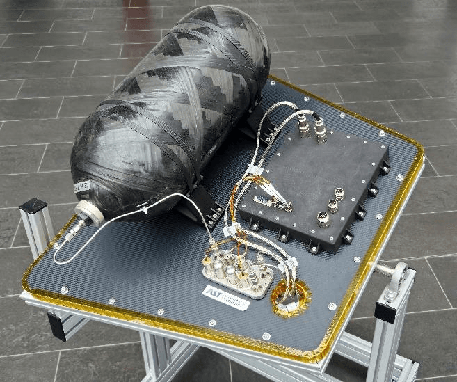
Another option is to perform a pre-assembly on system level. This can be achieved by using a satellite panel which will not participate in the structural integrity of the S/C itself. Otherwise, a reduced pre-assembly is possible using a temporary structure (e.g. aluminium profiles) to preassemble just the section between the tank and the thruster (consisting of fluidic management, FDV and piping) while these two components are directly integrated to the S/C structure. The pre-assembled system can then be transferred to the satellite. The advantage for both pre-assembled options is that the preliminary integration can be completed regardless of the S/C status. Furthermore, additional tests and inspections can be carried out on system level.
4.3. Testing on Subsystem Level
The HP-FCU will have seen a full acceptance test sequence before delivery. However, it is necessary to conduct additional testing on subsystem level to guarantee that also the connections between all participating components are pressure proof and leak tight. Therefore, the welding seams should be part of an investigation by proof pressure tests. In addition to proof pressure tests, visual and X-Ray inspections of the welding seams can be executed.
4.4. Launch Preparation
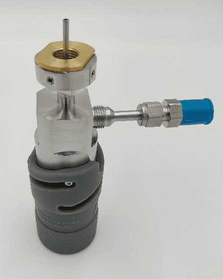
Before launch the filling of the satellites tank is conducted through the FDV with an associated ground half coupling (GHC). During tanking it must be considered that the Joule-Thompson-Effect leads to a cooling of the propellant. Therefore, an adapted flow rate must be determined beforehand to prevent a violation of the temperature limits. Furthermore, it is important to consider that the difference in temperature of the propellant from filling to ambient temperature (after the completion of the filling process), leads to different pressures for both states.
4.5. LEOP
During the launch itself, the HP-FCU is in off-mode, acting as low-leakage barrier between the tank and the thruster.
For the HP-FCU, no in-orbit calibration is necessary. Before the operational phase, only a priming with a duration of less than one minute is required. The intermediate volume and downstream fluidics are unpressurized during launch. The priming describes the phase in which the first actuations of the valves lead to a filling of the components, before the regular control algorithm comes into effect. Afterwards the HP-FCU is operable.
4.6. In-Orbit and EOL Operation
During the orbital phase the HP-FCU is in ON-Mode to allow the thruster operation. The propellant stored in the tank is distributed through the unit with a regulated flow to the thruster. The mass flow and the split ratio between anode and cathode are fixed by design following customer requirements. The mass flow and the performance are held constant throughout the entire operation. This is realised by a switching algorithm of the unit’s valves. Previous lifetime tests of the first generation HP-FCU, lifetime tests on component level and extensive in-orbit heritage show a reliable longtime operation of the flow controller. The performance is not affected by the tank pressure. Therefore, the HP-FCU can supply the thruster with propellant until the tank is reaching its lower limit, defined by the required mass flow and setpoint.
For some missions, a transfer to a graveyard orbit at EOL is required. After reaching the destination and before shutting down, the satellite is depressurized. For this purpose, a manual override should be implemented to allow for the venting of the tank through the HP-FCU. While during operation it is strictly prohibited to open both valves at the same time, for the venting operation the override should open both valves to depressurize the EP-Subsystem. With this operation the EP-Subsystems life cycle ends.
5. Summary and Conclusion
This paper gave an overview about the current status of the second generation of AST’s flow control unit HP-FCU. The unit was subject to a qualification test campaign. The results of the tests demonstrate that the unit is verified for proof and burst pressure and against relevant environmental conditions, with the health and performance of the unit not being affected by these tests. While the lifetime test is still ongoing, the functional tests already showed a strong performance with low mass flow ripple for a broad pressure range. The HP-FCU demonstrated robustness, reliability and high performance throughout the qualification test campaign.
Following the life cycle phases and two example designs the possible integration of the HP-FCU into EP-Subsystem modules was evaluated, to provide a first guideline for the design and integration of the subsystem. Fluidic, thermal, electrical and mechanical aspects were listed that should be considered when designing a subsystem using the HP-FCU. The paper showed how the unit can be successfully implemented into compact EP-Subsystems. The HP-FCU enables a simplification and the possibility of high volume series production of such subsystems.
6. References
Dandaleix, L.; Lopez, P.; Lebeau, S.; Harmann, H.-P.; Dartsch, H.; Berger, M.; Cautru, G.; Sabia, M.; Kroboth, D. (2022). Pioneering EP Fluidic Feed Systems from Constellation Success Stories. IEPC-2022-584. International Electric Propulsion Conference 2022.
Larson, W.J.; Wertz, James, R. (1999). Space Mission Analysis and Design. Third Edition, ISBN: 978-0-7923-5901-2.
Berger, M.; Harmann H.-P. (2022). Propellant Management Units for Electric Propulsion Thrusters in Series Production and in Update for New Applications. SP2022_#244. Space Propulsion Conference 2022.
Paper No.
SP2024_211
Published
2024
Conference
Space Propulsion 2024 · Glasgow, Scotland · 20–23 May 2024
Authors
Thomas Brus, Marcel Berger
Keywords
propellant management, flow control unit, HP-FCU, EP Subsystem, EP Modules, serial production, xenon, krypton