Ground Support & Measurement Equipment
SP2024_546
Development of a Standard for Absolute Mass Flow Measurement for Use with Any Type of Common Gas
Space Propulsion 2024 · Glasgow, Scotland · 20–23 May 2024
Ahmed S. Hashad, Heiko Dartsch, Hans-Peter Harmann
2024
Mass Flow Measurement
Calibration
Electric Propulsion
Abstract
AST developed an in-house gravimetric mass flow calibration setup achieving accuracy below 0.05% for gases including xenon, addressing measurement errors when conventional nitrogen-calibrated flow meters are applied to alternative propellants.
1. Introduction
The precision of propellant flow regulation in electric propulsion systems is crucial due to spacecraft’s limited propellant budgets: variations in mass flow rate can significantly impact trajectory, fuel consumption and mission duration, and deviations can compromise system stability and performance. Conventional industrial mass flow meters are typically calibrated with nitrogen gas; when using alternative gases like xenon, readings must be adjusted using flow-dependent conversion factors that vary between meter types and are often derived from theory rather than real measurement, particularly for exotic and costly gases like xenon, resulting in errors of a few percent – significant for missions such as Mars Sample Return requiring large quantities of xenon. To address this, AST developed an affordable in-house calibration setup, the Gravimetric Mass Flow rate (GMF) rig, ensuring precise control of pressures, temperatures and flow conditions.
2. General Approach
Mass flow rate is the change in mass over time (ṁ = m/t). This approach is feasible if the rate of change in flow is small compared to the measurement device’s response time and temporal resolution, allowing time integration, and if the amount of gas inside the test setup not directly measured (e.g. in the pipework) is the same at the start and end of measurement. Beyond precise measurement of consumed gas mass, the main design objective is therefore to ensure identical pressure, temperature and gas-density conditions at the beginning and end of the test.
3. Setup Design
The GMF setup includes two gas containers, Vol 1 and Vol 2, with the components inside a temperature-controlled environment stabilized to ±0.1°C by an air heater, keeping pressure sensors and needle-valve flow resistors at constant temperature. Vol 2 contains the gas whose mass is measured before and after the measurement; Vol 1 fills Vol 2 with gas via a hand valve prior to measurement, with a second hand valve allowing prior evacuation. Before measurement begins, the setup is operated from Vol 1 until stable equilibrium flow conditions are established; two solenoid valves and a pressure sensor form a pressure regulator maintaining pressure by briefly opening below a threshold, with a first pressure controller regulating from a 50 bar inlet to 5 bar with ±0.050 mbar fluctuation. Pressure ripple is negligible due to synchronization with measurement time; a second pressure sensor monitors inlet pressure, a needle valve and additional volume dampen ripple, and a commercial pressure controller practically eliminates fluctuations below ±2 mbar.
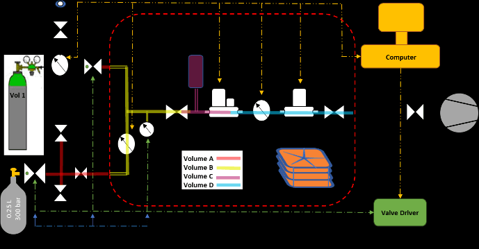
4. Calibration Sequence
The sequence is: evacuate Vol 2; fill Vol 2 with the supplied gas to 20-50 bar; disconnect and weigh Vol 2 including its valve after filling; reconnect and evacuate the connecting volume; test for leakage and open the connecting hand valve; identify measurement time and calibrate the mass flow meter valve using the needle valve; start the pressure controller using Vol 1 until stability; start the measurement by switching the pressure controller to Vol 2; record pressure, temperature and flow during the measurement time; disconnect and weigh Vol 2 again after measurement stop; and calculate the absolute mass flow rate.
5. GMF Uncertainty Sources
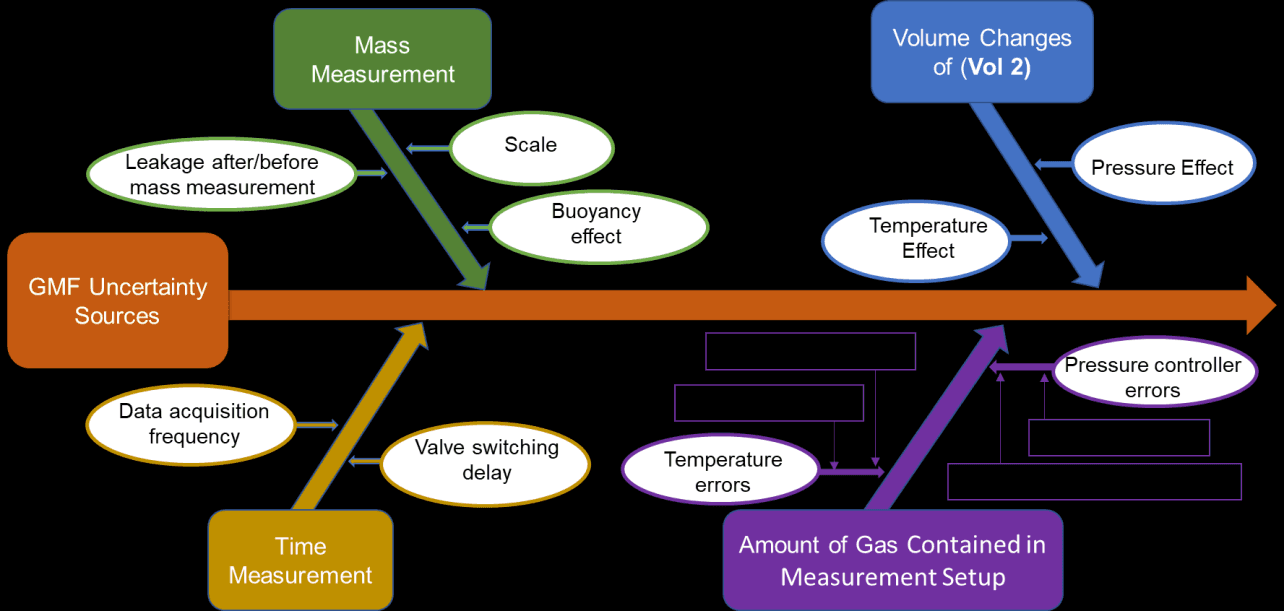
The overall relative error of the mass flow measurement combines independent time-related and mass-measurement-related contributions. Time measurement uncertainty arises from detecting pressure-level crossings to start/stop measurement, with a worst-case valve-timing uncertainty of 10 ms contributing a relative flow error inversely proportional to measurement time, plus a sampling-related contribution depending on the acquisition frequency of the instrument under calibration. Mass and volume measurement uncertainty includes the weighing scale’s repeatability (1 mg) and linearity (±2 mg), buoyancy effects from the container’s carbon-fibre-wrapped stainless-steel construction (corrected via outer diameter and length measurements before each weighing), and negligible valve-leakage contributions (better than 1×10⁻⁶ scm³/s He-equivalent, translating to less than 0.1 µg/second loss even for relatively heavy gases like xenon). Gas contained within the measurement setup is analysed by dividing the rig into four temperature/pressure sections (Volumes A-D); since gas density is approximately linear in pressure and temperature for all calibration gases (N2, Krypton, Xenon) at the near-room-temperature, low-pressure-differential conditions used, temperature- and pressure-related mass uncertainty contributions for each section are combined as worst-case (correlated) or sum-of-squares (independent) as appropriate, feeding into an overall relative mass flow uncertainty that is inversely proportional to the total mass transferred through the instrument being calibrated.
6. Validation Results
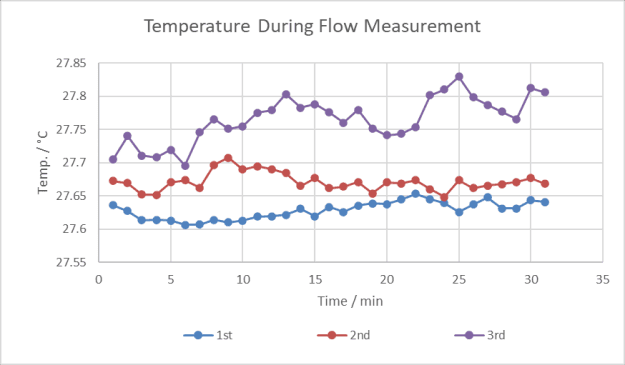
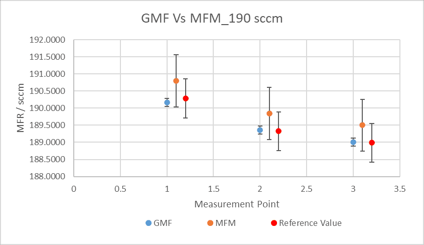
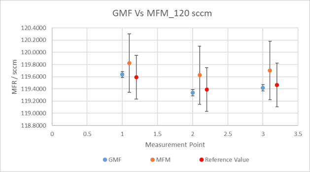
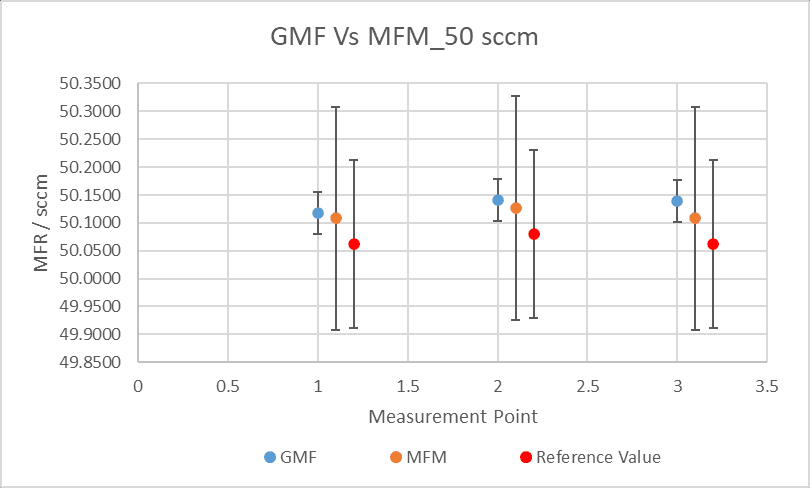
Temperature stability of the GMF setup during flow measurement was about ±0.2°C across measurement cycles. The GMF was compared against a calibrated 200 sccm commercial mass flow meter (MFM) using nitrogen at three flow rates (190, 120 and 50 sccm), showing full agreement between both standards within the stated accuracy of the mass flow meter used for comparison. The minimum achievable error is determined by the amount of gas stored in container Vol 2 (nominal volume 250 ml, worst-case without pipework and valve); assuming a container pressure not exceeding 50 bar (rated for 300 bar) and a maximum start/end pressure difference of 5 bar with a worst-case temperature difference of 23°C±5°C, the achievable calibration error for different gases was calculated: N2 12.58 g usable mass / 0.0225% error; He 1.75 g / 0.0611%; Ar 18.41 g / 0.0212%; Kr 42.02 g / 0.0190%; Xe 90.76 g / 0.0138%.
7. Conclusion
An affordable setup was developed at AST for in-house calibration of flow measurement equipment with any common type of gas, relying on quantifying the mass of gas depleted from a container over a defined period while ensuring the same amount of gas is used from the container and passed through the device under calibration. Error analysis covered methods to ascertain calibration uncertainty from pressure and temperature stability, requiring precise control throughout all parts of the setup and stable flow conditions established before measurement. The full error budget showed an accuracy better than 0.05% achievable with any commonly used electric-propulsion gas, validated by comparison against a commercially calibrated mass flow meter using nitrogen, making the system versatile across a wide range of gases.
Paper No.
SP2024_546
Published
2024
Conference
Space Propulsion 2024 · Glasgow, Scotland · 20–23 May 2024
Authors
Ahmed S. Hashad, Heiko Dartsch, Hans-Peter Harmann
Keywords
mass flow rate measurement, flow controllers, thrusters, electric propulsion, gravimetric calibration, xenon