Product Designs and Development
IEPC-2015-365 / ISTS-2015-b-365
Development of a Miniaturized Pressure Regulation System mPRS
Joint Conference of 30th ISTS, 34th IEPC and 6th Nano-satellite Symposium · Hyogo-Kobe, Japan · 4–10 July 2015
Hans-Peter Harmann, Swenja Rothaus
2015
Pressure Regulation
Electric Propulsion
mPRS
Abstract
AST developed the mPRS, a miniaturized electronic pressure regulator providing in-orbit adjustable outlet pressures from 1 to 25 bar at up to 350 bar inlet pressure, using the fluid-SMD technology.
I. Introduction
An electronic pressure regulator provides a flow-independent outlet pressure and an in-flight adjustable set point – advantages over a mechanical regulator that are usually paid for with increased mass, size and large pressure ripple. AST Advanced Space Technologies GmbH develops a new miniaturized electronic pressure regulator (mPRS), funded by the European Commission’s FP7 program, to overcome these drawbacks, based on AST’s fluidic surface-mounted-devices technology (fSMD) already used for a miniaturized xenon flow control unit. The new regulator shall provide an in-flight adjustable outlet pressure between 1 and 25 bar at inlet pressures up to 350 bar. During the first year, major processes such as high-pressure-proof electron beam welding were developed and verified, and feasibility was demonstrated for an elegant breadboard model (EBB), tested with lab equipment and in a full functional line including the mPRS, a flow control unit, and an ion thruster (RIT-22 and µN-RIT).
Target Missions and General Design
Target missions split into two categories: chemical propulsion systems requiring gas flows up to 25,000 sccm at 20-30 bar outlet pressure from a Helium tank at up to 350 bar; and a xenon-fed electric propulsion scenario requiring a tank pressure of 180 bar with adjustable outlet pressure between 0.1 and 3 bar, gas flow from 1 sccm (micropropulsion) up to 200 sccm (high-power thrusters), with upcoming full-electric satellites requiring flows of 1000-2000 sccm to supply Xenon cold gas thrusters from the same low-pressure node. The mPRS uses a two-stage design: a first stage reduces tank pressure to a roughly controlled intermediate pressure (either a mechanical pressure regulator – hybrid baseline – or an electronic bang/bang reduction stage – full-electric baseline), and a second stage performs fine control to the adjustable output pressure. The hybrid mPRS has already been built as an EBB using a standard mechanical gas-bottle pressure regulator as first stage and a low-pressure valve as second stage; the full-electric baseline is designed and analyzed pending availability of mPRS high-pressure valves.
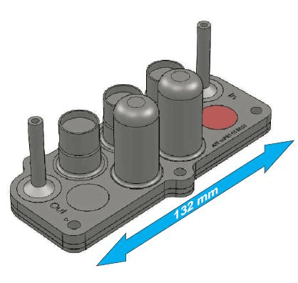
Fluid SMD (fSMD) technology replaces discrete components and pipework with a flow path board (FPB) occupying the role of the PCB – a multilayer stack of plates with integrated flow channels welded by a hot-pressing diffusion bonding process into a solid, vacuum-tight piece of stainless steel 316L with a 3D-network of channels, with components welded directly into holes on top of the FPB. The basic diffusion bonding process for 316L was developed during a former xenon flow control unit project.
II. Project Overview
The project spans three phases, one per project year: system engineering, design, and assembly/manufacturing process development; component development and viability demonstration of the baseline concepts with test-facility preparation; and pre-qualification of one of the two baselines, with the decision to be taken end of 2015. Major objectives include: miniaturized high-pressure valves, a high-pressure flow path board and miniaturized high-pressure sensors of European origin; an advanced miniaturized pressure reduction system of European origin; reducing internal leakage of flow components to less than 10⁻⁶ scc/s GHe; proving feasibility of fluidic-SMD subsystems for high-pressure applications; and reaching TRL5+ for the mPRS unit.
Assembly Processes and Component Status
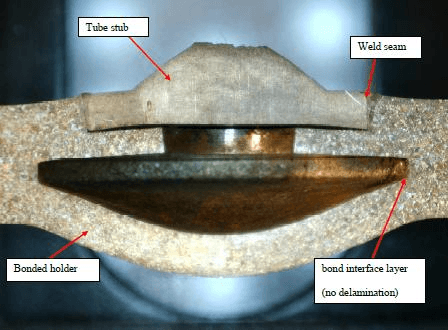
Right from project start, development focused on the diffusion bonding process of the flow path board and the electron-beam-welding joining technology between components and FPB, with process parameters highly optimized through extensive testing to fabricate vacuum-tight, pressure-proof joints validated for burst pressures exceeding 2000 bar, with micro-section analysis showing no fractures or crystallographic weaknesses even after testing at 1200 bar. The mPRS consists of a flow path board, particle filters, tube stubs, pressure sensors (low- and high-pressure), valves, and electronics. FPB feasibility has been demonstrated at breadboard level with a design for the first EM finished and manufacturing planned mid-2015. 5µm-grade particle filters have been developed and tested for filtration grade and gas flow capability. Two types of pressure sensors (up to 50 bar and up to 400 bar) with stainless steel membranes were manufactured at breadboard level, with EM sensors undergoing factory acceptance tests mid-2015; the viability of a diffusion barrier against long-term Helium drift is under investigation. The key high-pressure valve for the full-electric baseline targets small size, fast response and low power, with a lifetime target exceeding 100 million actuations (already demonstrated up to one billion cycles for the low-pressure version of the same valve type); by mid-2015 the design phase was complete and parts production ongoing, with first valves expected Q4/2015. Electronics were designed and manufactured at breadboard level in 2014 and successfully powered up.
System Development (EBB)
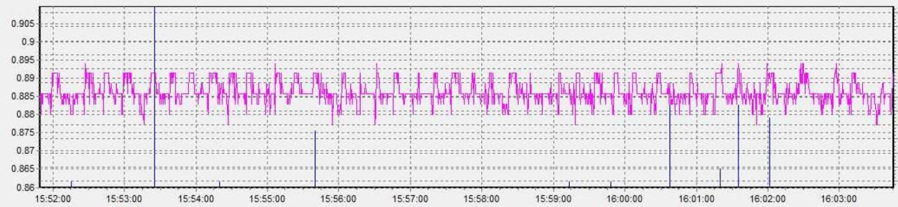
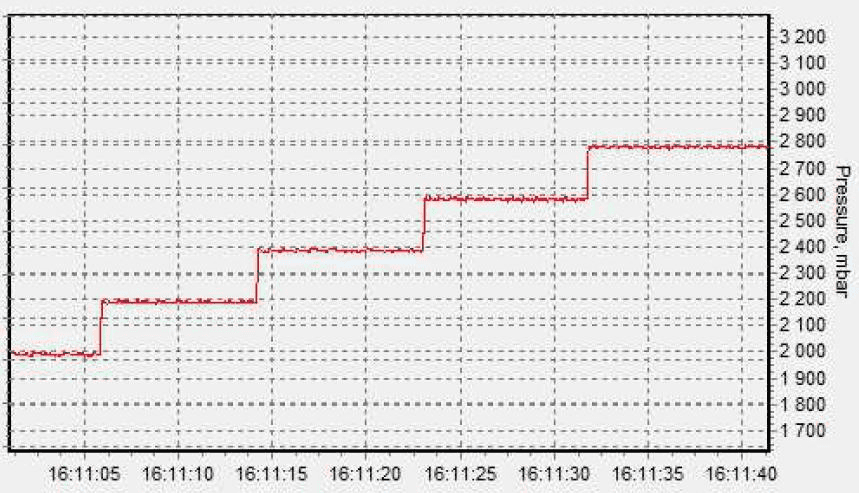
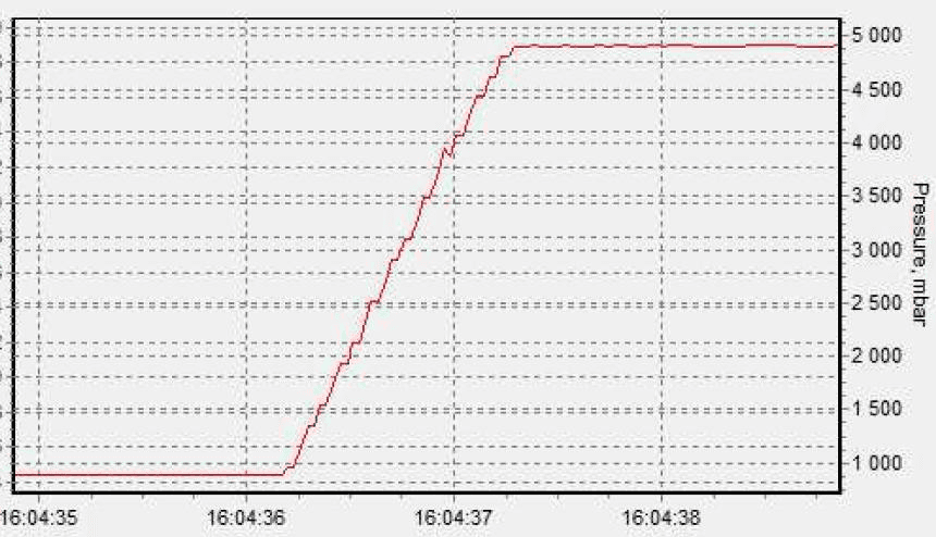
In the first project year, an elegant breadboard model of the second-stage regulator was manufactured to verify the overall operational concept, using a simple gas-bottle pressure regulator as first stage with an intermediate pressure of 8 bar and a low-pressure valve giving an adjustable outlet pressure from 0.8 to 7.5 bar, controlled by an algorithm implemented in an AST unit tester ensuring fast response without overshoot; although the valve is a simple on/off solenoid type, regulation proved very precise, stable and showed merely no ripple (±5 mbar, equivalent to less than 0.1% full scale). The EBB has since become standard equipment within AST’s lab for precision measurement set-ups, e.g. testing µFCUs for micropropulsion, providing side-benefit performance data within a relevant operational environment. In one demonstration supplying a µFCU with xenon at a constant flow of 0.3 sccm and a set pressure of 0.885 bar, the EBB showed very stable operation with a ripple of ±5 mbar even as flow demand increased to 60 sccm, with only the control valve opening more frequently. Set-point step response tests (both small 200 mbar steps and a large 4 bar step) with xenon and nitrogen showed fast adjustment without overshoot, with nitrogen’s lower viscosity giving an even faster response.
Coupling Tests with Ion Thrusters
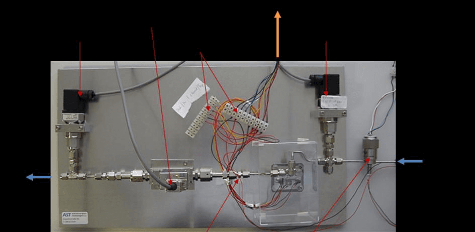
The EBB mPRS second-stage regulator was installed into the functional line of an electric propulsion system during ground tests, demonstrating operation of AST’s flow control unit (EQM3) together with the RIT-22 ion thruster from Airbus DS: with the flow control system outside the vacuum chamber, the regulator adjusted the µFCU’s inlet pressure to the optimum value, and the EP system operated at xenon flows up to 45 sccm. The same concept was used with a small RIT for micropropulsion, this time with the µFCU (EQM3) inside the vacuum chamber and the EBB regulator outside, supplying an inlet pressure between 0.8 and 1.5 bar for xenon flows between 0.2 and 1.5 sccm. In both coupling tests the full functional flow line performed without flaw, fulfilling operational requirements; the full-scale flow capability of the µFCU was scaled by a factor of 30 through inlet pressure adjustment, and combining the mPRS with the µFCU in future systems would enlarge the throttling capability to 1:150 and above.
III. Outlook
By the end of 2015 all components are expected to reach EM level, enabling a full-electric mPRS EM to be manufactured and tested. In the project’s last year, the mPRS will undergo the full range of environmental tests required to demonstrate readiness for a formal qualification program.
Paper No.
IEPC-2015-365 / ISTS-2015-b-365
Published
2015
Conference
Joint Conference of 30th ISTS, 34th IEPC and 6th Nano-satellite Symposium · Hyogo-Kobe, Japan · 4–10 July 2015
Authors
Hans-Peter Harmann, Swenja Rothaus
Keywords
miniaturized pressure regulator, mPRS, electric propulsion, fluid SMD, flow path board, electron beam welding